Announcement 01/16/2014: Currently, the HTML text version of the book (the stuff you see below) has not been updated to the 2nd Edition. The downloadable PDF files do contain the 2nd Edition of the book, so I would recommend downloading those instead of reading the version on the website. Hopefully I'll have the HTML version updated soon.
Note that the web address in the book and on the Lulu sales page currently points to the old location of this site (prometheus.vndv.com) which I do not control anymore. Sorry for the confusion.
If you want this tutorial as a downloadable PDF file, it is available in a print version (approx. 11.4MB) and a web version (approx. 1.6MB). The text is the same across both versions; the print version contains higher-resolution images and is formatted to print correctly for binding. The drawing on page 87 is also available here (approx. 160KB) in full scale.
If you wish to purchase a hard copy of the book, it is available through Lulu in paperback and spiral-bound versions. Note that I make only a few cents from the sale of each book: they're made available primarily as a convenience to people who want hard copies. In accordance with the license terms (legalese is available through the link below) you are permitted to print your own copies if you wish (or to convert into other formats such as ebook formats), as long as you don't try to sell them or otherwise profit from them, and as long as you don't try to claim it as your own work.

The Hobbyist's Guide to Casting Metal by Ben Baker is licensed under a Creative Commons Attribution-Noncommercial-Share Alike 3.0 United States License.
Table of Contents
- Disclaimer
- Safety
- Safety Gear
- Special Precautions
- Safe Foundry Practice
- Dictionary of Metalcasting Terms
- A-C
- D-I
- J-P
- Q-S
- T-Z
- General Info
- Judging Temperature
- Furnaces
- Crucible Furnaces
- Solid-Fuel Crucible Furnaces
- Propane-Fueled Crucible Furnaces
- Oil-Fueled Crucible Furnaces
- Electric Crucible Furnaces
- Sand Molding
- Construction of a Basic Propane Furnace
- Construction of an Advanced Propane Furnace
- The Use of Commercial Refractory Products For Hobby Furnaces
- Castable Refractories
- Firebricks
- Ceramic Fiber Products
- Rigidizers and Reflective Coatings
- Propane
- Supply and Fittings
- Burners
- Making Crucibles
- Steel Crucibles
- Ceramic Crucibles
- Appendices
- Appendix 1: Temperatures By Color
- Appendix 2: Melting Points and Pouring Temperatures of Various Materials
- Appendix 3: Fluxes
- Appendix 4: Composition of Selected Aluminum Alloys
- Appendix 5: Ceramic Chemistry Overview
- Appendix 6: Different Casting Processes
- Appendix 7: Flame Temperatures and Energy Densities of Selected Fuels
- Appendix 8: Identifying Scrap
Disclaimer
A lot of the stuff in this book is very dangerous. I make an attempt to point out some specific safety precautions as they come up, but there is no way I can point out every conceivable danger. I'm not a professional foundryman, scientist, or engineer, just a hobbyist--so there may be dangers that I don't even know about. For that matter, any advice I give could be wrong or even dangerous in certain situations. I can't be held responsible for any harm that comes to person or property as a result of following my advice or using any of the information on this website. Remember, the extremely high temperatures that liquid metal can reach are more than enough to send you to the hospital or kill you, or to set fire to anything nearby (like your house). Other activities, like welding or machining, present their own dangers, again very serious.
Safety
Casting metal is serious business, and very dangerous. Even when using proper safety gear, and observing all necessary precautions, serious accidents can still occur. Lack of proper safety gear, unsafe surroundings, or unsafe procedure increase both the likelihood and severity of accidents.
Safety Gear
Clothing
When casting or working with hot materials, always wear cotton or wool clothing. Synthetics can melt and burn vigorously when exposed to high temperatures, whereas cotton only smolders and wool tends to self-extinguish. Wear long sleeves and long pants with a minimum of holes, and leather work boots with thick soles. Keep the boots laced loosely so you can take them off in a hurry if metal gets inside. Commercial foundry boots often have Velcro fasteners instead of laces, the point again being quick removal. Shorts and open-toed shoes (or worse, bare feet) are a recipe for disaster.
In industrial foundries, workers wear heavy fireproof aluminized chaps, aprons, jackets, and gloves to protect against both radiant heat and molten metal splash. Such an outfit would be ideal for the hobbyist as well, but a full set of safety gear can cost hundreds or thousands of dollars. Welding safety gear is typically leather, and while it will not protect against pounds of liquid metal (such as in a crucible failure), it will help considerably against smaller splashes. A full outfit will cover the front of the body from head to toe (except for the face, which I'll get to later), and costs between thirty and sixty dollars.
Gloves deserve special mention. Ordinary leather work gloves are too thin, and synthetic gloves are worse than nothing at all. Leather welding gloves are heat-resistant to a degree (typically for short contact with surfaces up to 400 F), and are what many beginners use. Intense radiant heat (such as when melting iron) or prolonged exposure to furnace exhaust can either burn the gloves and damage them permanently, or heat up the insides enough to cause burns to the wearer's fingers. They are, however, excellent for lower-temperature operations like pouring aluminum and general foundry work, and they are very cheap, between $3 and $12 a pair.
Real foundry gloves are much more expensive, between $30 and $80 a pair, and most of the materials they are made out of (woven ceramic fiber such as Zetex) are not nearly as resistant to mechanical damage as leather. They are, however, much more heat resistant--the ceramic outer lining does not burn or melt under any normal circumstances, and they are typically several times better-insulated than welding gloves. They can be obtained in several different types, some designed for harsh mechanical conditions (typically Kevlar/Nomex) with a lower maximum temperature, some designed for maximum protection against hot objects (woven ceramic fiber, possibly with a double palm or extra insulation), and some designed for protection against radiant heat (aluminized gloves--be warned that contact with extremely hot objects can damage the aluminum coating).
Eye Protection
A full-face shield is necessary for metalcasting to protect against splashes of molten metal. Commercial foundry shields are often wire mesh, which has the advantage of not melting easily in hot environments compared to common polycarbonate face shields. Other types are made of tempered safety glass. For the hobbyist, a polycarbonate shield should be acceptable. Polycarbonate reflects infrared light quite well, so it will take a fair amount of hot furnace gas to melt the shield--it is unlikely to melt from radiant heat alone in a hobby situation.
A face shield does not offer complete eye protection--a pair of glasses (shatterproof polycarbonate lenses only) or safety goggles should be worn underneath. Side shields are strongly recommended. Safety goggles alone are not suitable either, since they do not protect the rest of the face.
Shaded lenses are necessary for iron melting, and recommended for bronze and copper melting, due to the volume of light released, and the increasing intensity of dangerous ultraviolet light at those higher temperatures. Sunglasses offer only marginal safety--ANSI No. 3 to No. 5 shaded lenses should be used. Oxyfuel welding goggles are of the correct shade and commonly available, but tend to dangerously block out peripheral vision. A tinted face shield, or face shield with flip-down tinted visor, is a superior solution. These may be a bit hard to find, and should sell for $10 to $25. When using a tinted face shield, the work area must be well-lit or movement becomes hazardous. Arc welding lenses (including the auto-dark variety, which can be triggered at random by a hot furnace or melt) are much too dark and should never be used.
Respiratory Protection
Propane and electric furnaces are extremely clean by themselves, and of all common metals, only a handful emit harmful fumes when melted, so a good portion of hobby melters can forgo respiratory protection. Waste motor oil can produce small amounts of vaporized lead (from the bearings in engines), most waste oil burners tend to produce smoke on startup, and solid fuels produce particulate ash. (All fuels except for electric still produce CO2, so ventilation is important for all furnace setups.) These hazards can be dealt with by staying away from and upwind of the source, and by melting outside where there is plenty of ventilation.
More severe hazards come from the metals being melted. Zinc, when overheated (as in zinc-bearing copper alloys), boils and reacts with oxygen to produce zinc oxide smoke. This can produce an unpleasant condition known as zinc fume fever. Zinc fume fever is highly unpleasant, but generally not dangerous, and zinc does not accumulate in the body, so this respiratory hazard can be avoided by using a cover slag on bronze melts and staying away from the distinctive white smoke and metallic smell. P95 and P100 particulate filters are effective in removing zinc fume from the air.
Lead and cadmium, when overheated, produce extremely toxic metal vapors. Not just any respirator cartridge is effective in filtering out these vapors—only P100 particulate filters remove a sufficient percentage of the contaminants to be safe. The primary defense for the hobbyist is to limit exposure by keeping melts short and the temperature as cool as possible. Small children are much more susceptible to heavy-metals poisoning than adults, and should be kept far away from any area where lead is melted or worked. See “Lead” under “Special Precautions” for more information.
Contact with siliceous refractory in its dry powder form, silica-based parting dusts, or dry powdered clay also constitutes a respiratory hazard. Keep these materials cleaned up—careless spills on the floor can release microscopic particles of silica every time they are walked over. Some of the smallest particles may stay in the air for hours. Silica, unlike asbestos, is not carcinogenic, but it does cause an unpleasant cumulative disease known as silicosis. Again, P100 particulate filters are necessary to remove high concentrations of these materials from the air. Nuisance dust masks are not even slightly effective, and are actually worse than useless because they provide an illusion of protection that does not actually exist.
The fumes from lost foam casting, or melting dirty, oily, or painted scrap, are usually fairly toxic and should be filtered out with an OSHA-approved organic vapor respirator. Chlorine-based degassing products release gaseous hydrochloric acid and chlorine gas, and should be protected against with a respirator cartridge rated for these two gases. Combination cartridges are often available that are rated for organic vapors, reactive gases such as HCl and chlorine, and come with a P100 particulate filter attached.
Note that disposable paper masks are only suitable for nuisance dusts such as sawdust—fine particles of silica and smoke particles are small enough to pass right through the masks. Not all respirator cartridges are created equal—don't assume it will protect you unless it's specifically rated for the hazards you need it to guard against.
Special Precautions
Lead
Everybody knows that lead is toxic, and that eating it or breathing its dust is a bad thing. But how bad is it? It turns out that ingestion of lead is unlikely to cause harm in adults (only a small portion of ingested lead is retained by the body), but small children are more likely to retain lead, and it does them more harm. The primary spread of lead contamination is through contact: picking it up on the hands. Ordinary soap does not do an adequate job of removing lead contamination; a mild acid such as vinegar should be used in addition to a thorough hand washing with normal soap, especially before activities like preparing food for small children. Lead can also be spread through secondary contact; e.g. door handles.
Lead vapors are also a concern when melting lead. Not all respirator cartridges can screen out lead vapor; respirator cartridges rated for metal fume (P100 particulate rating) are more expensive, but a good idea. In any circumstances, the lead should not be overheated or kept molten for longer than necessary, and it should always be melted outside.
Lead dust is a concern when sawing or filing lead. A cold chisel is preferred, but if sawing or filing is necessary, use a blade with large teeth and go slowly, with adequate lubricant, to create large chips instead of dust. (Fortunately, lead generally makes chips instead of dust.) Lead should not be sanded without proper dust-collection equipment. The lead chips should be cleaned up and disposed of, not left lying around.
Lead dross is also a hazardous material, even more so because it is in powder instead of lump form. It is difficult to legally dispose of, and should be kept in labeled, sealed containers to prevent contamination.
Zinc
Zinc, unlike lead, is not harmful at room temperature. It does, however, have a low boiling point of 1665 degrees Fahrenheit, so it should not be overheated when melting. Since its melting temperature is much lower, at 788 degrees Fahrenheit, heating to the boiling point is difficult to do accidentally. The real danger comes when melting bronze with zinc in it, because the melting temperature of the bronze is greater than the boiling point of zinc. The zinc vapor, when exposed to the air, immediately burns into white zinc oxide smoke. Inhaling this smoke is not generally lethal, and has little potential for long-term damage, but can cause a highly unpleasant acute condition known as metal fume fever. Glassy slags should be used when melting bronze to keep zinc vapor to a minimum, and the melting should always be done with excellent ventilation. Zinc fume has a characteristic smell, and the white smoke is often visible, so the best course of action is to simply stay away from it.
Magnesium
Magnesium is quite dangerous due to its high reactivity and its similarity to aluminum. Magnesium burns in air, water, and even the carbon dioxide used in common fire extinguishers. It can also react with sand, so even burying it in sand won't put it out. The only sure-fire way to put out a magnesium fire is with inert gas such as argon or sulfur dioxide. Since most hobbyists don't have the equipment to extinguish a magnesium fire, the best thing to do is not let it get lit to start with. (If you plan on melting and casting magnesium, you should have the equipment to deal with a fire.)
The best cure in this case is prevention: learning to distinguish magnesium from aluminum. Magnesium is about 36% lighter than aluminum, and will fizz in a mild acid such as vinegar, while aluminum does not. If you do end up with a magnesium fire, the best thing to do is to stand back and let it burn out. It may destroy your crucible and even your furnace, but you're likely to get injured if you try to move a crucible of burning magnesium. (If you get splashed with burning magnesium, it will keep burning as it eats its way into your body, since people have plenty of water in their bodies for it to react with.) Magnesium oxide smoke can also cause metal fume fever (see entry on zinc above).
Safe Foundry Practice
Steam Explosions
Steam explosions deserve special notice, since they are some of the most dangerous accidents, and some of the most common. Any time water comes in contact with molten metal, the water will flash to steam, expanding around 1600 times in volume almost instantly. This can easily throw metal, ranging from small droplets to fist-sized globs, tens of feet in any direction. Steam explosions are most dangerous when confined against a nonporous surface, such as a wet ingot mold. This creates a mortar of sorts, launching the metal forcefully. A damp concrete surface is another candidate for severe explosions, which can also launch bits of hot concrete as the surface spalls. Damp dirt or grass is usually porous enough to dissipate generated steam, and sand is extremely porous, so even very wet sand will result in at most minor spattering. A sand bed is a good idea for fire-prevention reasons as well, but it is the best surface for preventing steam explosions.
Steam explosions can also occur if damp tools, scrap, or flux is added to the melt. If the moisture stays on top of the melt, the metal is not thrown upwards, and any droplets of metal are small. If the moisture is submerged, however, it can throw the entire crucible full of metal out of the furnace. Scrap with recesses or cavities that can hold water, grease, or oil are usually the causes of such explosions—always preheat scrap before shoving it under the surface of the melt, especially if it might be wet. Certain fluxes (containing calcium or magnesium chlorides, usually) are hygroscopic and thus likely to contain water when put on the melt. Avoid these if possible—they are dangerous to use. If using them is necessary, preheat them before adding to the melt, and never shove them under the surface or stir them into the melt until you are sure all water is gone.
Even if a surface appears dry, it can still have chemically bound water. Common culprits are the hydrates in concrete and hydrated rust on steel tools and molds. These release water more slowly and less energetically than liquid water, but they can still be very dangerous. A general rule is to preheat ingot molds where possible, and store molds and tools in a dry area. If a mold has gotten wet, it must be preheated before being used again.
Crucible Care
Only the best and most expensive safety gear can protect against significant amounts of spilled metal, and even top-quality stuff will have trouble preventing serious injury if you dump a crucible full of metal on your feet. Therefore, the best course of action is to prevent spills in the first place. Part of that is taking care of your crucibles.
Steel crucibles should be preheated to a cherry red before using to prevent them being dissolved by the metal. If your crucibles have a brazed joint (such as on a propane tank crucible), it is a good idea to weld over the joint, just in case. Soup can crucibles are naturally unsafe (too thin to be used safely), and if used, should never be used more than once. Steel crucibles for bronze and copper need to be at least schedule 40 pipe to prevent deforming from the much higher heat. Never use a crucible that has eroded to much thinner than its original thickness, and always test for soundness before each melt.
Ceramic crucibles (except for SiC, which does not absorb water) must be preheated at 200 F for 30 minutes before each use, to get rid of any water that could crack or stress fracture the crucible. They should be evenly supported by their base block, and tools should always fit well around the middle (never the rim) of the crucible. Never lift a ceramic crucible with pliers, or use a crucible that is visibly cracked, has been dropped from a significant height, or otherwise abused. The empty crucible should “ring” somewhat when tapped—a dull “thunk” indicates stress fractures. (Clay-graphite has decent acoustical damping ability compared to mullite or other homogeneous ceramics, so this test may be of limited use with clay-graphite.) Never leave a heel to solidify in the bottom of the crucible or wedge scrap in tightly—thermal expansion will crack the crucible. Also, endeavor not to freeze the melt by adding scrap too quickly, and be gentle when skimming slag and poking the melt. If in doubt, don't use a crucible—a new one might be expensive, but it's worth the cost if it saves a trip to the emergency room.
General Safety Rules
Keep a clean melting area, with a short, clear path between the furnace and molds. You don't want to trip while carrying a crucible full of metal. Also, keep a good footing and don't try to move a crucible that is too heavy. Hold the crucible away from your feet, so if it spills or fails, it won't spill on you. Always have your wits about you when casting—it's not something you want to be doing tired, distracted, or inebriated. Also, cast either outside or with a dedicated high-volume fume hood and fireproof casting area indoors. Outside is recommended—a safe indoor casting area could cost thousands of dollars.
Keep flammable items well away from the casting area. If you're using solid fuel, be aware that sparks can travel a long way, so don't fire up if your area is particularly dry. Keep a bag of sand around to put out flasks and such—you don't want to be spraying water on molten metal. A class ABC fire extinguisher should be kept on hand for oil fires if you're using WO or kerosene, and a class D if you're melting magnesium. Keep propane hoses out of the way of hot stuff (watch where the radiant heat from your lid is going), and shield them from heat and hot spatters where possible. Don't leave hot things where you might walk, or sooner or later, you'll step on one.
Most importantly, use common sense. I can't possibly foresee all the dangers you'll face, and neither can you—act prudently in all situations, and the danger will be minimized. Even if you're as safe as humanly possible, though, metalcasting is still a very dangerous hobby. Don't make it more dangerous than it has to be.
Dictionary of Metalcasting Terms
A
- Air belt
- A hollow "belt" around the outside of a cupola furnace which distributes the air draft amongst the cupola's multiple tuyeres.
- Alumina
- Alumina, Al2O3, is the highly refractory oxide of aluminum metal. It is a common ingredient in refractory materials. Sapphires and rubies are primarily composed of alumina with various other impurities of metal oxides that give them their characteristic colors.
B
- Baked sand
- Any molding sand formulation using a binder that has little or no green strength and must be baked or fired before casting. In these formulations, the binders are not reusable. There are some commercial binding resins that require a heating or activation step, but the most important binder for hobbyists is molasses, or a similar sugar mixture, which can be mixed with sand and baked in a household oven before casting. This formulation makes an excellent core, because the product has excellent strength after baking, but the high temperature of the molten metal destroys the bond and allows the core to collapse as the metal shrinks around it.
- Ball clay
- Ball clays are typically of high plasticity and reasonable purity. They are relatively high in silica, so they may be more sensitive to quartz inversions, but they are nearly as refractory as kaolins.
- Bentone
- A chemically-modified bentonite, it bonds with oil instead of water. Used in oil-bonded molding sands.
- Bentonite
- A clay, not used in refractory since it contains fluxes, but used in greensand since little is needed to give a high green strength. For most bentonites, about 10% by weight (the remainder being clean sharp sand) is suitable for greensand, whereas other clays may require 20-25%. There are two major types of bentonites, sodium (or western) bentonite, and calcium (or southern) bentonite, which is also called fuller's earth. There are also specialty white bentonites, which are specialty products and should not be used for greensand. Sodium bentonite is slightly more plastic than calcium, but both are suitable for greensand use.
- Bod plug (also bott)
- A clay-and-sand plug used to seal the tap hole of a cupola; it is chipped away with a pointed tool to allow the metal to exit the cupola. A similar arrangement can be used to direct-melt scrap in a burner-fired furnace, if care is taken to keep metal out of the burner.
- Burnout
- A term used to describe the initial stages of firing a ceramic containing combustible materials, which are literally burned out of the ceramic matrix. This stage must be undertaken very slowly to prevent combustion gases causing spalling or cracks.
C
- Castable
- Short for "castable refractory," it�s a commercial ready-made refractory material that is mixed and poured much like concrete.
- Chaplet
- A small piece of metal that is designed to support a core in a mold. The chaplet is placed in an area that will be filled with molten metal, and when the mold is poured, it fuses to the rest of the casting.
- Cheek
- Not always used, it is inserted between the cope and drag to mold complex shapes. Many cheeks can be stacked if necessary.
- Chill
- A piece of metal inserted in a mold to produce faster localized cooling. Chills can be used on heavy sections to reduce the need for risering, or to alter the mechanical properties of the material in certain areas.
- Clay-graphite
- A material used to make commercial crucibles, typically made by mixing a high-quality clay with 30-40% of its weight in graphite. Organic binders, such as tar or pitch, may also be used. The crucibles are fired for a very long time at a very high temperature to promote formation of SiC crystals, which increase thermal shock resistance and strength. This firing schedule isn't feasible to duplicate on a small scale, so homemade clay-graphite crucibles will have no greater strength than their clay/grog cousins.
- Coke
- Essentially pure carbon, coke is to coal as charcoal is to wood. Used in iron melting and forge work, where the sulfur in coal would make the iron brittle. Coke produces a very hot fire and is denser than charcoal, so less refueling is needed.
- Cope
- The top half of a greensand mold.
- Coping down
- When a pattern with an irregular parting line is molded, part of the line will be buried in sand. Coping down is the practice of carving out sand until the line is reached, creating a parting face that is not flat. When this is done, a large amount of draft should be used on the parting face so that the mold halves can separate easily.
- Core
- A piece of the mold that forms a cavity in the casting. Cores can be part of the mold, or they can be separate pieces that are placed in the mold. When cores are made separately, they are usually made with a stronger binder than the clay in greensand, so as to survive the extra handling required.
- Core print
- An indentation in a mold meant to receive the end of a separate core, so as to hold it in place when the metal is poured in.
- Crucible
- The pot that holds molten metal. Common homemade ones are made of steel or clay and sand; commercially made ones are usually clay and graphite or silicon carbide.
- Crucible furnace
- A furnace which uses a crucible to hold the metal and can be fueled in many different ways. It works by heating up the crucible within the refractory-lined furnace and adding metal until the required amount is molten in the crucible. The crucible is then usually removed to pour, but some crucible furnaces are designed so the entire furnace tilts to pour metal, and the crucible is a permanent part of the furnace.
- Cupola
- A direct melting furnace designed to process large volumes of metal in many smaller batches. The basic operating principle of a cupola is a refractory tube with multiple tuyeres and a bed of fuel, typically coke. As charges of metal and coke are added, the metal melts, drips through the bed of fuel, and causes the fuel to float up higher. The metal is drained from the well by opening a plugged tap hole at the bottom of the furnace; typically, a cupola can melt a batch of metal every five to fifteen minutes. Cupolas take skill and a great deal of work to operate, but they melt very large amounts of metal. A 10" bore cupola can produce 300 to 500 pounds of cast iron per hour, requiring several tons of molding sand and an army of molders and attendants to keep up with the flow of metal.
D
- Degassing
- Certain metals dissolve gas in their liquid state, such as aluminum, which dissolves hydrogen. If the gas is not removed, it will come out of solution on solidification and create gas bubbles in the casting. There are two primary methods of removing gas: mechanical agitation and chemical reaction. Mechanical methods generally bubble an inert gas through the melt, releasing the dissolved gas much like shaking a soda would release carbon dioxide. Simply stirring the melt can remove some gas (often noticeable on heavily fluxed aluminum melts as little pops of flame when the melt is agitated�since salt fluxes dissolve steam readily, they promote hydrogen dissolution into the melt), but rarely removes all of it, and can introduce other contaminants like iron. The other method, chemical reaction, adds a material to the melt that the dissolved gas will react with. In the case of aluminum, bubbling chlorine gas through the melt will remove hydrogen as HCl gas. In the case of copper, the additions of reactive lithium, zinc, phosphorous copper, or other deoxidizers will remove dissolved oxygen as a solid oxide.
- Diatomaceous earth
- Formed from the fossils of microscopic diatoms, diatomaceous earth is a highly porous silica-based material, and thus valuable as an insulating refractory. It is typically available as cat litter in pea-sized pieces. It can be somewhat more heat-tolerant than perlite, but does contain fluxes. Diatomaceous earth is also available in ground form (sold for pool filters) and can be used as a parting dust, but it carries with it an extreme risk of silicosis and should never be used without respiratory protection.
- Draft
- The slope of a pattern away from the parting face of a mold, so as to allow the pattern to be removed without damage to the sides of the mold.
- Drag
- The bottom half of a greensand mold.
- Drift
- The temperature rise between the measured temperature before pulling a melt and the maximum equilibrium temperature of the melt. The temperature rise is caused by the crucible being hotter than the part of the melt that is being measured. This is only an issue when temperature can be measured precisely in the first place, and occurs more with ceramic crucibles than metal ones due to their lower thermal conductivity.
- Dross
- Metal oxides and impurities within a melt, which float to the surface and must be removed by skimming. See slag.
E
- Eutectic
- When two or more materials are melted together, the combined melting point of the two materials is often lower than that of either material by itself. The ratio of the different materials that yields the lowest melting point is known as an eutectic composition. Eutectics generally do not take effect until the materials have been melted together. When heating finely-powdered materials, such as when sintering ceramics, no melting will occur below the melting temperature of the lowest-melting binary eutectic. Once a liquid phase is present in the material, ternary and higher-order eutectics can form.
F
- Fireclay
- Fireclays tend to be coarser, less pure clays than kaolins or ball clays, and have earned a bad name in the art ceramics world because of it. (Certain impurities, such as chunks of limestone, can spall in the kiln and destroy ware.) Commercial firebricks are typically made with a fireclay base. Fireclays are highly refractory, as are kaolins and ball clays.
- Flash
- A casting defect which forms as thin, foil-like metal at the parting line of the casting. It is formed as excess metal forces itself into any small gaps between the parts of the mold.
- Flask
- The box (usually made of wood) that supports the greensand during molding. Flasks have at least two parts: the cope and drag, with one or more optional cheeks.
- Flux
- A material added to the crucible that usually melts at a lower temperature than the metal and floats on top of the liquid metal. Fluxes can be used to protect the metal from reacting with the outside air. Flux can also mean a material that melts at a fairly low temperature and helps melt things that normally melt at a higher temperature. For instance, fluxes are bad when mixed with refractories, because they tend to make the refractories melt at a lower temperature.
G
- Gate
- A channel carved between the sprue and casting.
- Greensand
- Contrary to its name, greensand is not green. The "green" part refers to the fact that it has not been fired. A typical homemade greensand would contain 90% fine silica sand (such as "play sand" available at most hardware stores), 10% bentonite clay, and just enough water to stick the sand together.
- Green strength
- This refers to a material's strength in the green, or unfired, state.
- Grog
- A clay additive, usually bits of crushed fired clay, that adds abrasion resistance and thermal shock resistance, as well as reducing shrinkage on firing.
H
- Heel
- A small amount of molten metal in the bottom of the crucible, serving two primary purposes. First, it allows for lower losses in melting thin scrap because the scrap can be pushed under the melt surface before it has a chance to oxidize. A heel also improves thermal conduction from the crucible to the scrap, causing it to melt faster. Adding too much scrap to the heel at one time will freeze the heel and potentially crack a ceramic crucible.
- Hot shortness
- At a certain temperature, some metals become hot short, where the metal crumbles and breaks up without actually melting. Different metals have different points of hot shortness. A dramatic example is aluminum, which loses its strength and crumbles at a temperature several hundred degrees cooler than its melting point. Other metals, like steel, instead become progressively more malleable until they melt.
- Hydrate
- A chemical element or compound with water chemically bound to the compound. This water will exit the hydrate as steam upon calcining at a temperature that varies depending on the material, but is greater than the normal boiling point of water. Materials can have several different hydrates. For example, "alumina hydrate" could indicate Al2O3x3H20 (gibbsite), Al2O3x2H20 (bauxite), or Al2O3xH20 (diaspore). Most water-setting materials, such as Portland cement and plaster of Paris, use a calcined compound that combines with water to form a hydrate. This is important to casters because these materials can release that bound water, sometimes violently, if heated by contact with hot metal.
I
- Investment
- A plaster-like ceramic which is used to surround a wax pattern in lost wax investment casting.
J
K
- Kaolin
- A pure, refractory clay with high alumina content but low plasticity.
L
- Ladle
- A container used to hold molten metal, sometimes made of metal lined with refractory instead of a solid piece of ceramic as is typical with commercial crucibles. Steel ladles are also used, mostly for white metals. The main difference from a crucible is that the metal isn�t melted within the ladle; it is simply transferred to it from where the metal was melted, such as a cupola or reverberatory furnace, or a large crucible, for better control of a more manageable amount of metal.
- Lost wax casting
- This involves surrounding a wax pattern in an investment compound which then sets around the wax. The wax pattern is then melted out (thus it is lost), forming a cavity within the investment material into which metal can be poured.
- Lost foam casting
- A sacrificial foam pattern is placed into loose sand, and metal is poured over the pattern, vaporizing it and replacing it with metal. The process can also be done in a thoroughly vented greensand mold, which is termed the full mold process.
M
- Matchplate
- A pattern or patterns mounted on a molding board, usually with gates and runners, and sometimes with risers and sprue, attached. Used to align the two halves of complex patterns, and in production situations to simplify the molding process. A matchplate can be cast by spacing apart the two halves of an ordinary mold with steel bars or similar.
- Mesh size
- Mesh size is a method of classifying powdered or granular materials. A material that is 100 mesh, for example, would just barely pass through a sieve with 100 holes per inch. Mesh size numbers are identical to the numbered grits on sandpaper, which can be used as a reference for comparison.
- Molding board
- A board used under a flask, which supports the sand and pattern and creates the parting face of a mold. If the board is cut to accommodate a pattern, it is termed a follow board. If the board is used to support the sand in a flask that is already rammed, it is termed a bottom board.
- Muller
- A machine designed to properly mix greensand; it has a kneading action to remove lumps and even out the clay and water content. Mulling can be performed by hand, but it is laborious and the results are somewhat poorer than when done with a machine.
- Mullite
- An aluminosilicate that is hard, strong, and resistant to thermal shock. It has a very high melting point, and is a prime material for crucibles, hotfaces, and other high-temperature furnace apparatus. It can be made by firing a mixture of clay and calcined alumina such that the molar ratio is 3 parts Al2O3 to 2 parts SiO2.
N
O
- Oxide
- An oxide is the compound produced when an elemental substance reacts with oxygen. Metal oxides are denoted by appending an -a suffix. For example, alumina is aluminum oxide, Al2O3, and silica is silicon dioxide, SiO2. Most metals form oxides when exposed to air at high temperatures; in some cases, the oxides form a layer that protects the metal from further chemical attack.
P
- Pattern
- A piece, usually made of wood, that is in the shape of the final casting. The greensand (or other mold-making material) is rammed in place around it to create the mold.
- Parting dust
- A material that is dusted on the parting face of a mold (and sometimes the pattern) to prevent sticking.
- Parting face
- The face where two parts of a mold separate. This is usually a flat plane, but does not have to be.
- Parting line
- The line on a pattern where the parting face is designed to go. All parts of the pattern should slope away from the parting line. The line is usually straight, but does not have to be.
- Perlite
- A volcanic material used in gardening, it can be added to refractory in order to increase insulation. However, it lowers the refractory's melting point, as it contains fluxes. Shredded polystyrene foam is a superior alternative, providing the same or greater insulative benefit without the added fluxes.
- Petrobond
- A brand of oil bonded molding sand.
- Plastic
- A material that is plastic is capable of deforming and holding its new shape without losing strength. The more plastic a material is, the more it can be deformed without losing strength (tearing or cracking) during the move. Silly Putty, for instance, is a very plastic material.
- Plinth
- A brick or block that the crucible sits on. It holds the crucible off the furnace floor, allowing the burner�s flame to circulate beneath it and reducing heat loss through the floor of the furnace.
- Pouring basin
- An area at the top of a sprue which the metal is poured into. It is usually tapered downwards towards the sprue and a volume of metal can accumulate in the basin to supply the casting as it shrinks on cooling. Risers may have a similar "basin" on top to supply the cooling casting. Large pouring basins can be molded in a separate small flask half to act as a funnel. This is helpful for large crucibles or other scenarios where pouring accurately is difficult, but metal should be poured directly down the sprue when possible to minimize the amount of sand that washes into the mold.
- Pyrometer
- A type of instrument used to measure high temperatures. Optical and infrared pyrometers use visible or infrared radiation to measure temperature, whereas thermocouples use a junction of dissimilar metals to measure temperature with a type of thermoelectric effect.
Q
- Quartz
- A crystalline form of silica, it is a hard and strong mineral, but undergoes dramatic changes in volume at specific temperatures (dubbed "quartz inversions"). Refractory containing quartz is more susceptible to thermal shock than refractory containing only mullite crystals and alumina.
R
- Ramming
- The act of compacting a material with the use of a hard, blunt object. Greensand is rammed into molds, and the amount of compaction used is critical to the integrity and surface detail of the mold. Likewise, some refractories are rammed into place in furnace bodies.
- Refractory
- What furnaces are made of. It�s any material that can survive high heat.
- Reil burner
- Possibly the most common type of naturally aspirated propane foundry burner, this burner uses a venturi to draw in air from the back of the burner, and is an excellent performer over a wide range of pressures. It will operate at a minimum pressure of around 1/4 PSI, and a maximum of greater than 60 PSI. The design was pioneered by Ron Reil, and many other metalcasters have made variations or modifications to the same general operating principle. Most commercial naturally-aspirated burners (including the gas injectors on barbecue grills) operate using the same venturi principle and basic construction.
- Reverberatory furnace
- A type of direct melting furnace, which can be powered directly with gas or liquid fuel, or the hot combustion gases from solid fuel. It is lined with refractory and has a depression in the refractory to hold the metal in place of a crucible.
- Riddle
- A coarse sieve which can be used to break up lumps in molding sand when making molds.
- Riser
- A mass of metal connected to the casting, designed to supply it with extra molten metal as it shrinks. Risers can be connected through gates, similarly to sprues, or they can lead directly into the casting. If a riser is between the sprue and casting, it is referred to as a hot riser; if on the other side of the casting, it is a cold riser. Risers are often open to the air to help vent gases from the mold; a riser specifically for this purpose is sometimes called a vent riser or chimney riser. A riser that is not open to the air is a blind riser or shrink bob.
- Roll-over
- The act of turning a flask over to ram the other half, roll-overs are usually performed with top and bottom boards securely in place so as not to stress the sand.
- Runner
- A channel, generally longer and wider than a gate, that is designed to feed metal to multiple castings, or into different areas of the same casting simultaneously.
S
- Sand
- Everybody knows what sand is, but there is a lot of information about sand that the hobby caster needs to know. Suitable refractory sands contain mostly silica (quartz) or olivine. Clean silica sand is very white (red or brown colors indicate iron contamination), and olivine is green to black. Coral sand, or the sand produced by the weathering of shells, is largely composed of limestone and is not suitable for any foundry uses. This sand is also very white. Good foundry sand is relatively fine (90 mesh is ideal for molding sand; 75 mesh is suitable), and sharp. "Sharp" in the context of sand means that the grains are angular instead of rounded, giving the sand better green strength and higher porosity.
- Sandcasting
- Involves the use of oil or water bonded molding sands to create a mold into which metal is then poured.
- Shrinkage
- The distance that a material shrinks when it is cooled. This usually refers to how much the cast part shrinks upon solidifying and cooling.
- Shrink bob
- Also referred to as a blind riser, this is a mass of metal connected to the casting, designed to supply it with extra molten metal as it shrinks.
- Silica
- Silica, SiO2, is a common refractory mineral and the oxide of silicon metal. Its crystalline form is called quartz, and is what most types of sand are made of. Amorphous or fused silica lacks the inversions characteristic of the crystalline quartz, and is extremely resistant to thermal shock, but also unlikely to be available to the hobbyist.
- Silicon carbide
- Silicon carbide (SiC) is a highly refractory material used for crucibles. It has high thermal and electrical conductivity for a nonmetal, making it suitable for resistance heating elements and high-temperature items like crucibles, but not for furnace linings. It is extremely thermal shock resistant, but is unsuitable for iron melting because the metal dissolves it.
- Sintering
- Sintering happens when unfired ceramics are heated to near their melting point. The fine particles of clay bond to each other, filling in gaps and creating a strong but porous structure. If the ceramic particles melt, the material is fused instead of sintered, and the resulting product is glassy.
- Slag
- Slag is the collected impurities, oxides, and fluxes from a melt. The term has a meaning very similar to dross, which usually refers only to the oxides from a melt. When melting certain metals (brasses in particular), fluxes and glass-forming ingredients are often added to produce a slag layer on top of the melt, protecting it from oxidation and keeping volatile metals (namely zinc) from boiling off, as well as fluxing the melt. This layer can also be referred to as a cover flux. The terms slag and dross can, in most instances, be used more or less interchangeably.
- Snap flask
- A flask built with a hinge at one corner and a latch at the opposite corner, so that at the end of the molding process, the flask can be removed and reused on another mold.
- Sodium silicate
- Sodium silicates are a group of compounds, often collectively referred to as �water glass,� that are used to bind some refractories and molding sands, and as deflocculants in clay slips. When sodium silicate reacts with CO2, either in the air or supplied from a gas cylinder, it produces silica and soda ash by the reactions Na2SiO3 + CO2 -> SiO2 + Na2CO3 and Na4SiO4 + 2CO2 -> SiO2 + 2Na2CO3. When the bonded product is heated, the Na2CO3 decomposes into Na2O (soda, a flux) and CO2, which is released. Thus, the result is a refractory bonded by a fluxed glass mixture. Depending on the composition of the refractory and the ratio of binder to filler, the entire mix can liquid-phase sinter into a highly refractory material in which the flux content is of little significance. Bound molding sands do not need to be pre-fired before use (the silica is present as a binder before firing, and the evolved CO2 is of little consequence in porous bonded sand). When the sodium silicate is used as a deflocculant, its creation of a flux in the mix is again of little consequence; however, the reaction between sodium silicate and CO2 in air means that the slip should be stored in a sealed container and air not mixed in during the stirring process. Adding dry slip-cast pieces to a batch of slip will require some extra sodium silicate for similar reasons.
- Spalling
- Spalls are chips or flakes of material. Trapped or chemically bound water in concrete, plaster, house bricks, clay and uncured commercial refractory will turn to steam when sufficiently heated. If heated too quickly this will result in immense increases in localized stress within the material, which may result in material failure and spalls breaking away with explosive force.
- Sprue
- This is the inlet through which metal is poured into the mold. Sprues can be formed with a pattern, or cut with a hollow sprue cutter. A piece of thin-walled pipe makes a very serviceable sprue cutter.
T
- Tap hole
- The "spout" of a cupola; it is below the lowest level of metal in the cupola well, so that when opened (by breaking the bod plug used to seal it) all the metal inside flows out into the waiting ladle. It may be resealed with a fresh bod while there is metal still inside if the ladle becomes full. The drain hole of a crucible furnace can be moved to the side to act as a tap hole for direct-melting scrap.
- Thermal Shock
- This phenomenon happens when a material changes temperature rapidly. Thermal shock can easily shatter brittle glassy materials, but more loosely bound sintered ceramics are resistant to it. Metals are generally malleable enough to be virtually immune to thermal shock.
- Tuyere
- The entry point for the burner flame on furnaces with burners, or the air draft on solid-fuel furnaces. It is pronounced "tweer."
U
- Upwind
- A style of naturally-aspirated propane burner, this burner relies on air holes between the gas jet and flame to draw in combustion air. The turbulence created by this method of air delivery makes the burner unstable at low pressures, though it may be more stable at very high pressures (>50 PSI) due to the better mixing provided by that turbulence. The burner generally does not burn well below 15 PSI. Designed by Lionel Oliver.
- Ursutz
- A waste oil burner consisting of a metal shell lined with refractory to provide a combustion chamber, with an outlet for the hot burning gases to enter the furnace. Also known as a "hot box" style burner. Since primary combustion happens in a separate, smaller chamber, efficiency is lower, but the burner heats up more quickly than a burner that relies on a hot furnace chamber to maintain combustion. Pioneered by Lionel Oliver.
V
- Venting
- This involves providing holes in something so that gases such as water vapor can exit freely without building up and causing cracking. Sand molds are vented by thrusting a wire into the sand around the mold cavity; lost wax molds can be vented by attaching sticks of wax to the wax pattern, which also melt out to leave a "chimney" that allows gases out. Rammable refractories can be vented in a similar way as sand molds by thrusting a wire into them. This makes it easier for water vapor to exit the refractory on firing, reducing the likelihood of cracking.
- Venturi
- A venturi is a device consisting of two tubes of differing sizes, connected by a smooth taper (ideally a bell curve). As a fluid flows through the tubes, a pressure difference is set up (the small tube has a lower pressure and the large tube has a higher pressure) due to the effects of Bernoulli's principle. This is used to practical effect in naturally aspirated foundry burners, where the flow of fuel gas sets up a pressure differential and draws in combustion air from the atmosphere.
- Vitrify
- Vitreous substances are glassy and fully fused. Refractories should be sintered instead of vitreous; the loose sintered structure is more resistant to thermal shock than a vitreous structure is. If refractory vitrifies in use, it has gotten too hot.
W
- Waste Oil
- A foundry fuel that is usually free but difficult to burn, waste oil (WO) comes from two main sources. The first, waste vegetable oil (WVO), comes from fast food restaurants and your last fish fry. The second, waste motor oil (WMO) comes from the local mechanic and your last oil change. Be careful about burning used brake fluid, transmission fluid, etc., as it may have chlorinated oils that release toxic fumes. WMO may also potentially contain trace amounts of heavy metals (lead especially, from bearings in engines) that vaporize when burnt.
- White Metal
- Any of a class of metals with melting points below the temperature required to emit visible light. Lead, tin, and zinc are common examples.
- Woodgas
- Woodgas is the volatile vapor formed as wood is heated. This consists of water vapor and various organic fractions, including hydrogen, methane, and carbon monoxide. Woodgas can be produced and burned, using special apparatus, to fire a foundry in much the same way as an oilburner is used. Some of the production methods produce charcoal as a secondary product; some burn the charcoal to fuel woodgas production.
XYZ
General Info
Judging Temperature
Measurement of temperature is critical to the metal caster, both in correctly firing refractory and in ensuring that molten metals are at a correct pouring temperature. As a general rule, metal that is too cold will result in a partially filled mold or loss of surface detail; metal that is too hot may cause sand to stick to the surface of the casting (in sandcasting); problems with entrained gas and volatile metals boiling out of the alloy can also manifest themselves.
Heat By Color
Judging the temperature of an object by observing the color of its glow is a very low-tech and inaccurate method, but it finds a great deal of use in a hobby setting. Obviously, the object must be glowing visibly for this method to work; the properties of the glowing surface and amount of ambient light also factor in to the perceived glow. The best surface to view is a dark matte surface, such as the outside of an oxidized iron crucible. A closed object with a small hole for viewing (such as a closed furnace) also provides an acceptable surface to view, more or less regardless of the properties of the surface inside the closed object. Ideally, all glowing surfaces would be viewed in total darkness, but more practically, they should be viewed in the same lighting conditions, such as in the shade on a sunlit day, for consistency. Viewing in full sun tends to wash out even the higher temperatures, as does viewing a light or shiny surface (the reflective surface of molten aluminum is difficult to see glow, even when the crucible is glowing brightly), so these conditions should be avoided.
An estimation of the temperature corresponding to each color is as follows (assuming a matte black surface in the shade in daytime):
| Color | Degrees Fahrenheit | Degrees Celsius |
| Faint red (barely visible, depending on conditions) | 900-1200 | 500-650 |
| Dark red | 1200-1400 | 650-750 |
| Bright red | 1400-1600 | 750-870 |
| Orange | 1600-1800 | 870-980 |
| Yellow | 1800-2000 | 980-1100 |
| Yellow-white | 2000-2300 | 1100-1260 |
| White (off-white or yellow through a #5 shaded lens) | 2300-2600 | 1260-1430 |
| Blinding white (point where shaded lenses are necessary; white through a #5 shaded lens) | 2600+ | 1430+ |
Optical Pyrometry
An optical pyrometer is essentially a device for judging temperature by color, albeit far more accurately than the human eye can. The fundamental structure of the device is a dark tube with an incandescent bulb in it. The filament's temperature is controlled by a potentiometer, so that its glow can be matched visually to the glow of an object viewed through the tube. The device can be calibrated with the melting temperatures of various pure metals, and then used to determine temperature in the visual range (>1000 F in most circumstances).
Pyrometric Cones
Cones are devices used in ceramics to judge, not absolute temperature, but heat work, which is a function of time and temperature, and is necessary to determine how pottery is fired. Thus, a cone does not correspond to an absolute single temperature, but rather a range of temperatures depending on the heating rate and time spent "soaking" at that temperature. Cones are numbered sequentially, with 1, 2, etc. getting progressively hotter. Cones cooler than ^1 (the caret symbol denotes cone) are designated by appending a zero, with ^01, 02, etc. getting progressively cooler. A cone indicates its temperature by bending from the heat; when the cone has bent a full ninety degrees, that indicates the heat work corresponding to that cone has been reached.
In ceramics, ^02 is considered low-fire, ^6 medium fire, and ^10 high fire. Most commercial ceramics kilns go no higher than ^10 or 12. An un-fluxed clay-based refractory should be fired to ^18 to 20, and a good refractory clay should have a PCE (pyrometric cone equivalent, the amount of heat work at which a cone made from only that clay would bend appropriately) around ^35.
Proper cone charts are readily available through an Internet search, but more importantly for the hobbyist are some rules of thumb.
Given reasonable rates of heating, ^1 represents about 2100 F, ^10 2350 F, and ^18 2800 F. I recommend a 30-minute soak at 2800 F to fire any un-fluxed clay-based refractory. This provides good sintering without unduly wasting fuel. Slightly over- or under-firing will not damage the refractory. Too much over-firing will mostly waste fuel; with the temperatures that most foundry burners are capable of reaching (no more than 3000 F except under exceptional circumstances), it is impossible to vitrify an un-fluxed refractory. Under-firing will produce a weak product, and this error may not be possible to fix with a second firing, so erring on the side of too much heat is a good idea.
Furnaces
Furnaces, regardless of their type, need a few attributes to function properly. The first is refractoriness, or the ability to withstand heat. The second is insulative ability. While the first two are arguably the most important attributes of a successful furnace, attributes such as mechanical strength and flux resistance become important in some designs. Thermal mass is also an important consideration in furnaces that undergo a lot of cycling between room temperature and operating temperature.Refractoriness
Refractory is, after all, named after its defining attribute: its resistance to heat. Some homebrew refractories, however, aren't very refractory. Commercial refractories are rated by the temperature at which they incur damage, most pure clays such as fireclay, ball clay, and kaolin are suitable for well over 3000 degrees Fahrenheit, and common homebrew ingredients like perlite often start melting over a wide range, anywhere from under 2000 degrees to 2800 degrees, depending on the properties of the individual batch. Non-refractory ingredients like Portland cement melt considerably lower, and worse, they can flux the entire mixture, turning your furnace into a puddle of goo.
Since puddles of goo don't generally make good furnaces, it is important that the heat resistance of your chosen refractory is adequate to survive all conditions in the furnace without being damaged. The maximum temperature present in your furnace is not the temperature of whatever you're melting; it's usually wherever a burner (or other heat source) impinges on the furnace wall, and it can reach temperatures several hundred degrees higher than the melt, depending on the power of the heat source and the ability of the melt to carry heat away from that area. Generally speaking, if the furnace heats up slowly, and the heat source is evenly distributed, the peak temperature in the furnace will be very close to the average temperature. A pottery kiln, for example, should be able to fire pottery to very near the limits of the refractory without damage around the burners or heating elements. Conversely, if the furnace heats up quickly, and the heat source is concentrated, then peak temperatures could reach as much as twice the average temperature.
Insulative ability
Refractoriness is only part of the equation for a good furnace. Tungsten, for example, is highly refractory, but it doesn't make a great furnace because it acts as a heat sink, wasting large amounts of energy. A good furnace should keep the heat in, and that's where insulation comes in.
Air is a great insulator, but not if it can move around, forming convection currents. Most successful insulation, therefore, traps air in tiny pockets. The material that the insulation is made of should also be fairly insulative, but it won't be nearly as effective as the air it's keeping trapped. Therefore, the best insulators are light, fluffy materials with lots of air in them, such as the commercial insulating wool sold for kiln insulation (think fiberglass insulation, only it's designed to take high temperatures). A similar effect can be achieved by adding something burnable (like sawdust or little bits of polystyrene foam) to your clay-based or castable refractory. When fired, the bits of material burn out, creating little air pockets. Commercial foaming agents essentially do the same thing, trapping lots of little gas bubbles.
Commercial castable refractories usually come in two varieties: insulating and non-insulating. The insulating variety will be lighter and weaker than the non-insulating variety, which is very dense and hard to withstand lots of mechanical abuse. Typically, the insulating variety is mechanically strong enough for homebrew furnaces, and should therefore be chosen over the non-insulating variety due to its greater insulative ability.
Thermal Mass
Thermal mass isn't a big consideration in commercial furnaces that run continuously for long periods of time, but it's very important in homemade furnaces that get cycled up and down a lot. The problem is simple: Before your furnace can heat anything else up, it has to heat itself up first. If your furnace has a lot of material to absorb the heat, it's going to take a lot of time and energy to get hot, even if relatively little heat escapes outside of it. When it's done melting whatever it's supposed to melt, all that energy put in to getting it hot gets lost, as the hot furnace cools off.
Minimizing thermal mass is relatively easy to do. Materials that have lots of air in them have very little thermal mass, as well as being good insulators. Heavy, dense materials have lots of thermal mass and are best avoided under most circumstances. A rough rule of thumb is the material's density: Light furnaces are much better than heavy ones, as far as thermal mass goes.
Hotfaces
So far, I've only talked about furnaces made with a single material. Unfortunately, materials that are light and fluffy (good insulators with low thermal mass) aren't usually very durable. Materials that are hard, strong, and temperature-resistant are usually heavy and dense, with mediocre insulative abilities. A hotface is the easy way to get the best of both worlds, and are typically used for two reasons: to protect a highly insulative but weak material from mechanical abuse or chemical attack (e.g. fluxes), or to protect a highly insulative but not-terribly-refractory material from the hottest parts of the furnace's interior, such as the burner's flame. Hotfaces can also be used to stretch the budget, by protecting cheap insulation (like perlite) with a more expensive material.
Whatever you do, DO NOT make a hotface three inches thick, unless your furnace is thirty feet tall and you drop tons of scrap into it on a regular basis. Hotfaces should be as thin as you can make them and still have them fulfill their function. This goes back to the previous discussion of thermal mass. Your insulation is behind your hotface, so the hotface has to heat up and cool down with every furnace cycling. If the hotface is thick enough that the back side of it is still relatively cool by the time you're done melting, the insulation isn't doing anything.
Crucible Furnaces
Crucible furnaces are the most common type for hobby metalcasters. The only special design qualification for a crucible furnace is that it needs to fit a crucible. Instead of first building the furnace, then trying to find or make a crucible to fit it, I strongly recommend that you have a functional crucible on hand when you start designing your furnace. You should also be able to easily buy or make more crucibles of the same size. This will save a lot of trouble down the road, and since the furnace is designed to fit the crucible, it will run more efficiently and take less material than one that is too big. (One that is too small won't fit the crucible at all, and trying to enlarge a furnace after construction is more or less a gesture of futility.) This seems obvious, but many beginners try to build the furnace first, then have a hard time getting a crucible to fit it.
Also make sure to consider how you're going to get the crucible in and out of the furnace. Whatever lifting apparatus the crucible is designed to use should be able to lift the crucible out of the furnace without scraping against the walls or running into obstructions. Again, this is something you should think about before you build.
Furnace Shape
Crucible furnaces are usually shaped in a rough cylinder, with the lid being a flat disk that rests on top. Alternatively, the lid can have a recess to allow the crucible to extend above the sides of the furnace (for easier lifting), or the furnace can be built in three parts, with the walls lifted off the base to grab the crucible from the side. Furnaces should not generally be built in a "top hat" configuration, with the top and sides lifted as one piece off the base. The reason for this is that removing the side walls from around the crucible will cause it to cool quickly, so this should not be done for charging the crucible or skimming dross. The additional lid in the three-part design allows access to the top of the crucible without lifting the walls.
Lid Lifting
Lid lifting mechanisms can vary from the extremely simple (a pair of handles, suitable only if the lid is light enough to move easily) to the very complex (a system of slides and winches, usually used for very large and heavy three-piece furnaces). In between these two extremes, there are various types of pivots used for lids of moderate weight. Whatever the design, it should be easy to operate, robust enough not to wobble, and the hot side of the lid should not point toward a person operating the lid lifting mechanism, or in front of the furnace skimming dross. The lid can radiate a fair amount of heat (especially if it is large), and can make moving around the furnace uncomfortable or dangerous. It should also never point at fuel lines or electrical connections.
Solid-Fuel Crucible Furnaces
Many beginning metalcasters start by building a solid-fuel crucible furnace, because it offers arguably the quickest and cheapest way to get into the hobby. The primary reason is that solid fuel doesn't take any special apparatus to burn. All it requires is a source of air. Solid-fuel furnaces can reach high temperatures without using specialized refractories because the fuel provides some degree of insulation for itself. Many beginning furnaces use only a thin steel shell (e.g. a coffee can) or a terra cotta flowerpot (both poor insulators and not particularly robust), and they function acceptably well because the fuel in contact with the edges of the furnace never gets as hot as the fuel in the direct air blast.
The most primitive solid-fuel furnace is simply a wood or charcoal fire on the ground or in a fire pit, and such a fire can melt white metals and aluminum with ease. Fuel consumption is greatly reduced, however, if the fuel is contained within a proper furnace and forced air provided for a hotter burn.
Tuyere Placement
Solid fuel gets hottest when it is provided with adequate air for combustion. This will happen near the tuyere, where air enters the furnace. A tangential tuyere, as in a furnace designed to use a burner, will not provide an even heat; the wall that the air blast is directed toward will heat up, and the rest of the furnace (including the crucible) will stay cold. The best tuyere placement for an even heat is directly below the crucible, pointing up, but this creates problems in the event of a crucible failure, as metal will drain down into the tuyere. A solution might be to put a drain hole in the pipe leading to the blower, covered by a meltable or burnable plug such as aluminum foil or duct tape. A tuyere pointing directly at the side of the crucible may also provide a sufficiently even heat. A grate can be used to distribute the air evenly, but such a grate will be prone to oxidation.
Fuel Placement
Unlike in other crucible furnaces, solid-fuel furnaces do not use plinths. Instead, the crucible sits directly on a bed of fuel. This bed should be at least half the crucible diameter thick around the outside of the crucible, and somewhat thicker below the crucible. The crucible should be buried up to its rim in fuel. (Nestling the crucible back into a burning fuel bed after a pour is somewhat difficult; the undertaking is aided by thick gloves and long-handled pliers.) For maximum temperature, the entire fuel bed should be burning evenly. Fresh fuel should be added evenly around the top, no more than one layer thick at once. Fuel pieces should be big enough to allow free passage of air, but small enough to provide good contact with the crucible.
Air Blast
Hair driers, vacuum cleaners, and leaf blowers are often conscripted to provide the necessary air blast to run a solid-fuel furnace. The first of these may not provide enough air, while the latter two often provide too much. A shutter of some kind, either to vent excess air or to restrict the blower's intake, should be used to control the air blast. Excessive air can rapidly oxidize the bottoms of steel crucibles, creating failures often mistaken for melting. Too much air also wastes fuel.
Efficiency
Solid fuel tends to self-insulate, so good furnace insulation is less important with these furnaces than with other types of furnaces. Fuel usage can be greatly reduced, however, by a furnace that is the proper size and shape. Using extra fuel in place of a proper container is relatively costly, as the fuel burns whether it's melting metal or not. A well-built furnace with a proper lid can also save a good deal of fuel, as compared to one with little or no insulation. Well-built furnaces also tend to last longer, as well. Keep in mind that the refractory must be mechanically strong and relatively resistant to fluxing (ash is a flux) to handle solid fuel over a long lifespan.
A good deal of fuel can also be saved if combustion is halted at the end of a melt. The easiest way to do this is to cut off the air supply, which may not be effective if the furnace leaks. An alternative is to shovel out the hot coals and quench them, but this is a hot and messy job. Water should never be sprayed into the furnace unless the intent is to crack the furnace into small pieces. Regardless of the method, ash should be removed before the next firing. Coals will burn better if the ash isn't plugging the tuyere and taking up space, and there's less of a respiratory hazard when the blower is turned on.
Propane-Fueled Crucible Furnaces
Crucible furnaces that are heated with a gaseous-fuel burner (predominantly propane, but also natural gas) all share certain design requirements. One is the tuyere placement. The tuyere should be placed so that the outer edge is tangential with the inner wall of the furnace, and the vertical centerline of the tuyere should be even with the bottom of the crucible.
Rules of Thumb
Since gaseous fuels are among the most expensive fuel sources, furnaces using these fuels should be as efficient as possible. One of the most important ways to increase efficiency is to size the furnace correctly.
- For every cubic foot of enclosed space inside the furnace, the burner should output approximately 100,000 to 200,000 BTU/hr.
- The vent hole should be from 1/2 to 1/3 the inside diameter of your furnace, or 2 to 3 times the inside diameter of the tuyere.
- The walls of the furnace should be as close as possible to the crucible (with adequate room to operate the lifting mechanism, of course), but the gap between the crucible and furnace walls should never be narrower than 3/4 the burner tube diameter.
- The gap between the top of the crucible and the furnace lid should have approximately the same area as the vent hole for maximum efficiency. If you want to calculate the distance between the rim of the crucible and the furnace lid exactly, use this formula: Where x is the diameter of the vent hole, the distance between the rim of the crucible and the furnace lid is (1/2 x)2 / x. If you don't like math, then just eyeball it at somewhere around a third the vent hole diameter.
- The drain hole diameter should be slightly less than the burner tube diameter.
- The plinth should be no taller than twice the tuyere diameter.
- The tuyere diameter should be about 1.4 times the burner tube inside diameter. If the burner has a working flare, use the largest inside diameter of the flare.
- The furnace wall thickness should be about a third the furnace's inside diameter for adequate insulation.
Oil-Fueled Crucible Furnaces
The burning of waste cooking or motor oil is advantageous to the hobbyist with a limited budget, as it is usually a free or very inexpensive fuel, but the additional requirements of dealing with a liquid, hard-to-burn fuel necessitate a considerably more complex burner design than required by gaseous or solid fuels. There exist almost as many different oilburner designs as there are hobbyists in the field, and the burners tend to be cantankerous and highly tailored to a single, unique setup. Building a working oilburner is beyond the scope of this manual, but I will briefly touch on the furnace requirements for successful oil combustion.
The general layout of an oil-burning crucible furnace is similar to that of a propane-fired furnace, with a tangential tuyere, lid, and vent hole above the crucible. The furnace needs to have more space for free airflow than with a propane furnace, as oilburners are generally more sensitive to backpressure. This means a larger tuyere, more space around and above the crucible, and larger vent hole. The combustion of an oilburner tends to happen in the furnace as much as in the burner, and tends to be more violent than with gaseous fuels, so a hard, durable hotface is advisable. With free fuel, efficiency is somewhat less of a concern, and denser, more durable refractories can be used. Oil combustion can get as hot as or hotter than the best propane burner designs, so refractory, especially in the burner itself or in the tuyere region, should be rated to at least 3000 F.
Electric Crucible Furnaces
Electricity is a clean way to melt, and generally less expensive and more readily available than other fuel sources. Unless a high-amperage dedicated circuit is available, however, the power output will be low, leading to slower melts than with other fuels. Elements capable of high-temperature melting are quite expensive, so resistive electric melting is best reserved for aluminum and white metals instead of the higher-melting metals. The vagaries of element selection, and the intricacies of induction and arc furnaces and other exotic types of melting equipment are again beyond the scope of this manual, but the furnaces required for electric resistance melting are quite simple.
Again, standard furnace rules of thumb apply with electric furnaces. The major differences are the absence of a tuyere and vent hole, and the presence of grooves or other supports for electrical elements. Not all ceramics are electrical insulators at high temperatures; high-alumina ceramics generally perform well, whereas high-silica ceramics may lead to leakage currents through the refractory. The addition of a removable plug in the furnace lid for charging and skimming dross is advisable and will increase efficiency compared to removing the entire lid for these operations. Finally, the generally slower melting of electrical furnaces means that adequate insulation is vital. Insulation is generally thicker on electric furnaces than on other varieties.
Sand Molding
Pattern Making
There are three critical parts to know about before making a pattern to be molded and cast in sand. First is something called the "parting line." The seam between the cope and drag is the parting line, and the pattern's widest portion must sit at the parting line.
Often, you will want to make "split patterns." This is basically a pattern that is in two halves that meet at the parting line. Alignment pins are installed in the halves. There are ways, however, to cast 3D objects without a split pattern. Patterns with a flat side can be molded only in one half of the flask. If  the pattern's projection is small or shallow, it can be molded with a board designed to accommodate it (known as a "follow board"), or molded normally and the sand carved down to the parting line (known as "coping down").
The second thing you have to know about is "draft." Draft is where side portions of the pattern have an angle that allows you to safely withdraw the pattern from the sand mold without disturbing the sand. Draft is very important. Having completely vertical sides makes it very difficult to remove the pattern. In some parts, however, this may be unavoidable. Usually the best solution is to design the pattern with draft, and then machine the part to have its 90 degree angle afterward.
The opposite of draft is an "undercut," which for obvious reasons is impossible to mold in sand. Again, draft can be added and the part can be machined to finished dimensions afterward.
For some sand molds, you may need to use a three or more part flask, where there is an extra piece between the cope and drag. That would be called a "cheek."
The third thing to know about is shrinkage. Metal shrinks when it cools, and different metals shrink at different rates. To further complicate the matter, different alloys of the same type of metal shrink at different rates. This needs to be kept in mind when designing the pattern. Also, you may have to make parts larger still to allow machining of the part afterward.
Patterns for sand molds are best made of metal or wood. Wood patterns should be coated in a good coating of polyurethane to protect them, and keep them from absorbing moisture from the sand. This coating can be skipped for a one-off pattern, but molding is more difficult.
You don't have to be a good woodworker to make good patterns. Epoxy, putty, and anything else can be used to fix your screw-ups, as long as the finished surface is smooth and finished.
Preparing Sand
Molding sand is made with a mixture of clean sharp silica or olivine sand, and clay. I recommend 10% of the sand's weight in bentonite clay, but other clays will also work. Other clays will be less sticky, so more will be needed. After this mixture is made, water has to be added. It takes very little water (the sand should be damp, not wet), and it must be added slowly and mixed in thoroughly. Doing this by hand is possible but laborious; a muller is a better alternative.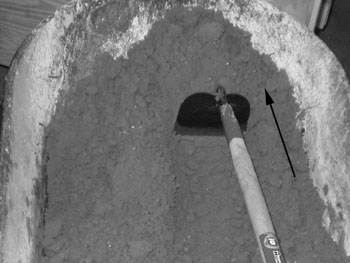
Once the sand is made, it can be reused for multiple molds, but it must be reconditioned after every casting. Again, reconditioning sand by hand is possible but laborious. If you have no alternative, what I find to work well for mixing and conditioning sand is a hoe and wheelbarrow. The sand is pushed against the slanted side of the wheelbarrow with a smearing action, then raked back to break up the now-compacted sand. Special care must be taken to break up lumps and stir the sand into itself so it is processed evenly. This motion is repeated until the sand is even, lump-free, and of the desired consistency.
The moisture level of the sand is perhaps its most important attribute, and the one that needs the most constant adjustment. Testing 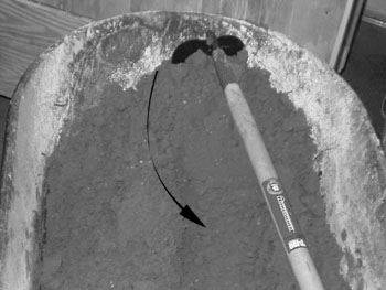 moisture is done with what is called a "squeeze test"--a handful of sand is picked up and squeezed into a ball. Sand that is too dry or lacks clay will not stay in the ball, but will crumble. Sand that is too wet will stick to your hand and feel wet. Sand that is the proper consistency will form a cohesive, fairly resilient ball without adhering to your hand; it should also pick up the texture of your hand (fine sands can reproduce fingerprints quite well) and break cleanly. An experienced molder will be able to tell not only the moisture content of the sand from this test, but also things like its tensile strength (by pulling the lump apart), compressive strength (by crushing one of the halves), and porosity (by blowing through the other half). To the novice, these relative measurements mean little without a reference point, but with experience in using your sand at different moisture levels and strengths, the tests will begin to mean more.
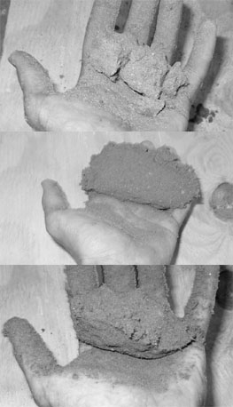 The moisture added to new sand does not absorb immediately; the sand will improve if left to set in a sealed container. If your sand seems to be wet enough, yet lacks strength, mull it up and let it set overnight, and see if it improves. The longer the sand sets, the better--sand that has been well-used and well-cared for, and that has been absorbing moisture for months, will be superb compared to freshly-mixed sand.
As mentioned, an automated muller is the preferred method for conditioning sand. It saves labor and does a more thorough job in less time. Commercial mullers tend to be expensive, but building your own is a task of no more than moderate difficulty. The action of a muller accomplishes the same thing as the illustrated action of the hoe above. The mechanism typically contains the sand in a drum, compacting it with heavy rotating wheels, and scraping it off the bottom and sides of the drum with a set of rotating plows. The rotating mechanism typically spins between 25 and 60 RPM, and takes quite a bit of torque to push through the sand. A muller with a 1 HP motor, spinning at 50 RPM, might be able to handle 30 to 40 pounds of sand per batch, and processing a batch typically takes about five minutes. The muller is unloaded with a trapdoor at the bottom.
Molding
There are a great number of ways to mold different patterns in sand, and choosing the correct sprues, runners, risers, and gates, and the correct orientation of a complex pattern is part science and part art form. Even experienced molders are sometimes unsure how to sprue a complex mold; the standard procedure in those cases is to pour a test piece, examining the casting afterward to see how the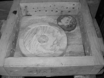 metal flowed and how the flow can be improved. Most of the knowledge necessary to do this is gained from experience, but the basics can be taught.
The series of photos accompanying this section are of a fairly simple mold of a pair of pulleys. In molding parlance, they are both molded in the drag, for an easy single-roll mold and less chance of a failed casting in the case of a gap run-out. This is particularly important in this case, since the flask is just a little bit too small for these patterns, and the patterns are dangerously close to the edge, and to each other. Those narrow gaps between the patterns and the edge are hard to ram properly, and they can easily spring a leak and pour molten metal out the side of the mold.
To start making the mold, the 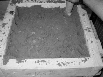 patterns are laid on the molding board and covered with parting dust. A light coat of sand is sprinkled on and patted into crevices by hand, then a heavier layer (about an inch and a half) is dumped in and rammed. After ramming the entire mold with the blunt end of the rammer, the peen (pointy end) is used to ram sand around the edges of the flask, and in gaps between the patterns. After the first layer is rammed by hand, the rest of the flask is rammed with a pneumatic rammer (the one shown is a modified air chisel). This part can be done by hand as well, but the power tool is much faster. The flask is struck off level and vented with a thin wire poked into the sand down to the pattern, then flipped over. Parting dust is applied, the sprue and riser are placed, and the cope is rammed much like the drag. It too is struck off level and vented, then the sprue and riser forms are pulled out. A pouring cup (like a funnel in the sand) is carved for
 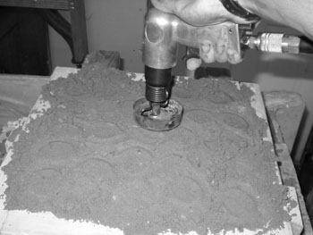 the sprue, and the top edges of the riser are rounded off to prevent them breaking and falling in the mold.
(A note about parting dust: I use silica flour, which works well but is a significant respiratory hazard--wear a mask! Other materials, such as talcum powder, chalk, or graphite dust, may work to greater or lesser degrees and present greater or lesser respiratory hazards. Commercial parting dust is a high-temperature plastic flour that is biologically inert, but it may also be expensive or hard to get. Any parting dust that absorbs water is unlikely to work well, and may cause casting defects.)
Then, the flask is opened and the patterns are pulled out. Gates (and, if necessary, runners) are carved, as is a well below the sprue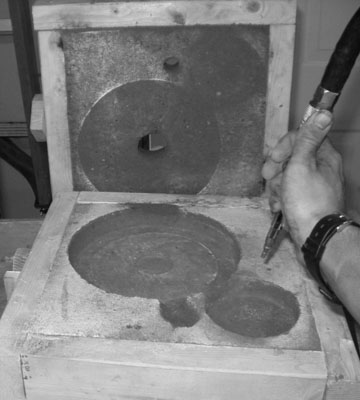 to trap sand washed into the mold. This well should extend below the level of the gate so debris does not get washed into the mold.
Note how, in this mold, the smaller pulley is fed from the larger one instead of directly from the sprue. Placing them so close together forced there to be a connection between the two, which can also serve as a gate. It would be better molding practice to move them apart (in a bigger flask) and gate each one directly from the sprue. Also note the dark patch at the far side of the big pulley. This is a little extra sand added to a loose edge to prevent a leak from forming there.
Now is the time to push down any loose edges and clean up any details. After the mold cavity is suitable, any dust is blown out (either with an air compressor and nozzle or with a hand-powered air pump or bellows--blowing dust out by mouth is a good way to inhale it) and the mold is closed up. It will be weighted before being poured, to prevent hydrostatic pressure from pushing the cope up and forcing metal out the gap. If the casting was formed in the cope, such a gap run-out would ruin it; this casting in the drag could conceivably turn out anyway. Casting in the cope, however, washes less sand into the mold and provides a smoother fill because the metal is rising up from below instead of pouring in from the side.
Construction of a Basic Propane Furnace
Furnace Body
My preference for insulating refractory is a mix of a high-temperature clay and shredded polystyrene foam, in a 1:4 volumetric ratio. This yields excellent thermal properties close to that of commercial ceramic wool, and is much less expensive. The clay/foam mixture is somewhat difficult to form into larger shapes due to its drying and firing shrinkage, and is more fragile when fired than its commercial equivalents, but these are sacrifices that the frugal hobbyist has to deal with. This mix, if it will be subjected to any rough treatment, should be faced with a thin layer of either a mix of 1 part clay to 3 parts sand, or a thin layer of a mullite ceramic. The mullite is the superior material, but more expensive to blend and perhaps somewhat less forgiving to the beginner.
Crucibles
Furnaces should generally be built to accommodate a specific size of crucible. Steel crucibles are adequate for the melting of aluminum and white metals, and more foolproof for the beginner to use than commercial ceramic crucibles. A good size of crucible for the beginner is about 4" diameter and 6" tall, which will hold about five pounds of aluminum. I use disposable 1-lb propane canisters as a convenient size of crucible. (Safety note�the propane must be completely bled out of the nearly-empty tank by depressing the valve until no audible hiss is heard. For extra safety, it�s recommended that you also unscrew the valve and fill the tank with water to displace the propane before cutting the tank. I take risks and just hack off the top with a chop saw once they�re completely empty, but I don�t recommend that.) These crucibles generally last about 20 melts apiece. For a longer-lasting crucible, you can screw a pipe cap onto a pipe nipple, or weld a piece of plate onto a steel pipe. The heavier the crucible is, though, the more fuel it will waste and the longer it will take to heat up.
For a crucible this size, the furnace should have an internal diameter of 6" to 6 1/2", and an internal height of about 8". A wall thickness of 2" of insulation, plus 1/8" to 1/4" of hotface, is adequate for a normal furnace. (Electric furnaces, or those that need to achieve extremely high temperatures, such as for iron melting, may do better with 2 1/2" of insulation.) The floor and lid should be the same thickness as the walls.
The Burner
Burner construction will be dealt with in a later chapter, but adapting the furnace to the burner is critical in furnace construction. For a furnace this size, a 1/2" nominal (pipe size) burner is adequate.
The furnace needs a tuyere to fit the burner. The tuyere also must perform the functions of a flare for the burner--i.e. it has to hold the flame at the burner's tip, preventing it from blowing out at high pressure and from burning in the tube at low pressure. For this, a straight-sided hole that provides a smooth sliding fit for the outside of the burner pipe will be adequate. If your burner is made of tubing with walls significantly thinner than black iron pipe, the tuyere may need to be a bit oversized. Also, the tuyere should be made so its outside edge is on a tangent to the furnace wall, high enough off the furnace floor that a crucible spill won't flood the burner, and low enough that the burner flame is pointing at the bottom corner of the crucible (on its plinth).
(A note on tapered flares: The taper, as far as I'm aware, produces no discernible benefit, and probably actually hurts burner performance compared to the sharp pressure "step" at the end of the burner tube. Why? Because when propane (or anything, for that matter) burns, the flame front travels at a specific speed. The design objective for a burner is to make sure that the gas within the mixing tube is traveling faster than the flame front (otherwise it'll burn in the tube), and the gas within the flare is traveling slower than the flame front (otherwise the flame front is outside of the burner, which doesn't work very well since once that gas starts mixing with ambient air, the fuel mixture shifts toward the lean end of the spectrum and the flame goes out). A smooth taper between too fast and too slow means that if the speed of gas going through the burner changes (with an operating pressure or choke adjustment), then the flame front moves around. At the ends of the pressure range, the front is very close to either the end of the flare or the end of the burner tube, and a bit of turbulence could "bump" it over the line. A sharp step creates lots of turbulence (which means an easier time burning in that particular spot) instead of the smooth laminar flow of a tapered design, and holds the flame front still, so it's less susceptible to this kind of instability.)
Construction
Note: This section applies mostly to furnaces built with the aforementioned clay/foam mixture. Other materials may have different requirements.
The first and most important thing to keep in mind when dealing with clay is that it shrinks. It will shrink during drying and during firing. Thus, it is important to take shrinkage into account both when sizing the furnace and when designing the forms. The refractory will shrink away from any forms surrounding it, and it will shrink more tightly onto any forms inside it. If inner forms are left in place during drying, they will cause the refractory to crack as the shrinkage pulls it apart. On the other hand, inner forms made of a nonporous material are prone to sticking to the clay. A sheet of newspaper wrapped around the form will prevent this, but the newspaper will stay stuck to the refractory's inside. This is important to consider if you plan to add a hotface after the forms are removed. Porous forms, such as those made of plaster, will not stick to the clay, but they are also considerably harder and more expensive to build. As such, they are best suited for use in making multiple furnaces from the same forms.
The clay/foam insulative mixture is best mixed dry (1 part clay to 4 parts foam by volume), then water is added slowly to make it plastic enough to form without getting it too wet. The less water added, the less it will shrink later. "Seasoning" it by letting it age in an airtight bag or container will improve its workability; optimum seasoning time is a week or two. It can be stored indefinitely, and as long as it stays wet, it will improve in workability with age. Dry mix can be crumbled up and re-wetted.
Clay/foam refractory cannot be poured like concrete; it must be rammed in place like greensand, only with less force than the average greensand mold would need. The idea is to compact it enough to stick the particles together and remove all air pockets without unduly crushing the foam. Venting the refractory with a thin wire will aid in the drying process.
Drying
The key to drying any clay-based ceramic without cracks is to dry it as slowly and evenly as possible. For the first stage of drying, cover the furnace with a plastic bag that has a few fist-sized holes to allow for slow air exchange. The bag should ideally be suspended away from the refractory instead of touching it; adding a towel to prevent condensing water from dripping on the refractory will help. Once the refractory is evenly moist, and has dried to about the "leather hard" stage (where the refractory is no longer plastic but is still noticeably wet), the bag can be removed for drying in still air, possibly with the aid of a towel or other porous covering. Once the refractory is bone dry throughout, it can be slowly heated with an incandescent light bulb or a source of warm dry air (such as a hair drier) before starting the firing. The larger the furnace is, and the thicker the refractory, the longer the drying process will take and the more difficult it will be to do without cracks. Very small furnaces may be able to dry without using the bag at all, depending on humidity level. Any cracks should be repaired as soon as they form--in later stages of drying, wetting the edges of the crack with a mist of vinegar will help the new clay stick.
Firing
The key to a successful firing is firing slowly. Temperature should stay at or below 200 F until all water has left the lining, and from there, should rise no faster than 1000 F per hour. Half that rate is still considered a "fast" firing in the ceramic world. A controllable burner is necessary to fire this slowly--the initial burner flame should be about the size of a candle flame, and from there, fuel pressure should be increased in increments of less than 1 PSI until the furnace reaches red heat, and any change should be given at least a half hour to take effect. The furnace should generally be fired empty. Blocking the vent hole, especially when the burner is very low, will help the heat stay even--any gaps or holes in the refractory will create cool spots.
Once temperature is reached--a blinding white heat if you are firing without commercially-made pyrometric cones, it should be held for at least a half hour. Turning the burner off and blocking all exits to the furnace will be adequate for cooling.
Construction of an Advanced Propane Furnace
The "basic" method of constructing a furnace--ramming the refractory in a single section and firing it in place--is cheap, simple, and easy, but has a few significant drawbacks. The refractory shrinks and the furnace shell (usually made of sheet steel) does not, so the refractory must either crack or pull away from the shell. Also, during firing, it is impossible to get the outside of the furnace hot enough to fire properly, so a good deal of the insulative layer will be perpetually fragile.
A far better method to make a furnace is to fire it in a kiln instead of firing it with its own burner. This allows for a more controlled heat, and ensures complete sintering. Of course, this method also has drawbacks. Its first major drawback is that it requires a kiln that can get to the temperatures needed to fire refractory, and that is big enough to fire the furnace evenly. The second issue can be circumvented somewhat by firing the furnace in pieces. Either way, however, the furnace must be fired outside of its shell, which would be destroyed by the firing process. Almost inadvertently, this restriction circumvents the problem of the furnace shrinking away from its shell--the shell will be built around the fired furnace, to the correct size. The only remaining problem is that of fuel consumption--even with a well-insulated kiln, heating up the entire kiln to fully fire the furnace parts will require far more fuel than simply heating the inside of the furnace. Therefore, furnaces made by this method will be more expensive to produce, additional equipment requirements notwithstanding.
Since the furnace will not be formed in its shell, a different forming method will be needed to make the sections which will be fired. In this case, we will borrow a forming method from slip casting--the plaster mold. To make the plaster molds, first make a pair of master positive molds--that of the top or bottom of the furnace (the molds are identical) and that of one-fourth of the furnace side. Both should have about two degrees of draft. I made the master molds out of polystyrene foam board, which can be quickly and easily cut with an electrically heated wire, glued together, and sanded smooth. They were then coated in grease to act as a release agent, and slathered with plaster mixed to a thicker-than-normal consistency. It took about a gallon of plaster for both molds. Be careful to keep the plaster coating as uniformly thick as possible--thin sections can easily form as the plaster flows and drips, and those thin sections will crack easily.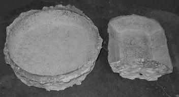
Once the plaster is dry, but before it sets up completely, trim the drippings flush with the surface of the master molds. Be careful, as it is very easy to crack the soft plaster. A coarse hacksaw blade is a valuable tool for this operation, and patience is a must. After the plaster finishes curing, pull out the master molds and scrub the grease off the plaster with soap and water. A grease-free surface is necessary for the clay to release properly. Once the molds are clean and have dried overnight, the clay can be compressed in place, smoothed to the top of the mold with a straight-edged tool, and left to dry overnight, at which point it will be dry enough to come out of the mold and hold its shape. These pieces can dry in open air unless they are very thick or the air is particularly dry, since all sides are open to the air and the pieces are considerably smaller than an entire furnace. Vent, drain, and burner holes can be cut with pipe or rolled-up sheet metal when the clay is "leather hard"--the same time it is removed from the mold. The hotface can be slip cast inside the same molds and trimmed to fit, cast in different molds (especially if it is thick enough for the radius of curvature to be substantially different), painted on the inside of the sections as they are de-molded, or added after the initial firing as a zero-shrink product.
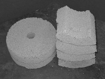 Once all pieces are bone dry, they can be fired. (See firing instructions under "Ceramic Crucibles.") After the firing, they can be assembled, either with commercial furnace cement, or with kyanite-containing mullite doped with 1-3% chromia. (Safety alert: chromia is toxic.) The chromia diffuses into the lattice of sintered alumina, acting as a bonding agent that allows the plastic clay to bond with the pre-fired ceramic. The kyanite expands upon its transition to mullite and silica (which is subsequently converted to mullite), making the recipe net-zero-shrink. Any seams inside the furnace should be coated with a thin layer of non-doped mullite (of the same recipe and applied while both are plastic) to prevent ceramic crucibles from accidentally sintering to the furnace.
In either case (with mullite or water-based furnace cement), soak the fired furnace parts in water, then coat all mating faces with the bonding material mixed to a plastic consistency, making sure to fill crevices and get good adhesion. The parts can then be stuck together, with more bonding material added as necessary to fill gaps. The material should be forced out of every joint, and can then be trimmed off and smoothed down with a moistened fingertip. This should be allowed to dry under a plastic bag for a time, then in open air, filling any cracks as they occur. Once it is all bone dry, it should be fired with its own burner to a minimum cone 18 (and a peak temperature higher than the hottest usage conditions) to make sure the kyanite expands suitably.
The Use of Commercial Refractory Products For Hobby Furnaces
Castable Refractories
Dense Castables
Dense castables are designed to line the insides of large industrial furnaces and ladles, where tons of scrap are dumped in at a time, the walls may see direct metal contact and corrosive fluxes, and the furnaces are designed to run eight to ten hours a day for years without repair or patching. A large industrial scrap melter might have a three to four inch thick hotface of dense castable in front of a foot or more of insulating castable or insulating firebrick. If you're thinking this is a bit excessive for the average hobbyist, you're absolutely right. Dense castables have no place in the large majority of homemade furnaces, because their high density and low insulating value wastes enormous amounts of fuel and slows melts considerably.
Most refractories, once fired, are made of aluminosilicates that have very similar density and thermal properties to each other, so as a crude estimate, one could say that the insulative value of a refractory is directly proportional to the amount of air trapped within the ceramic, or inversely proportional to the refractory's bulk density. In other words, less dense refractories insulate better than more dense refractories, and they also heat up faster, so they make furnaces more efficient. Dense castables range between 120 and 180 lbs/cf, some of the most dense refractories available. For a reference, most fired clay ceramics range between 100 and 160 lbs/cf, unless insulative material has been added.
Dense castables do have limited use in the hobby world, as a super-duty hotface for direct-melting reverberatory furnaces and large-volume scrap melters. They are nearly immune to fluxes and mechanical abuse, so they should be used only where this type of treatment makes them most practical. A hotface of 1/2" is sufficient for a furnace of 12" to 16" bore, which makes an exceptional hybrid crucible furnace and scrap melter. The hotface can also be made freestanding and the area behind it backfilled with loose insulation, such as perlite, diatomaceous earth, or bulk ceramic fiber, which has the potential to lower construction costs.
Like most commercial products, dense castables are considerably more forgiving to fire than clay, and do not shrink significantly on drying or firing, so they can also be used to patch cracks, and shrinkage does not have to be compensated for in furnace design.
All castables, unless a specific amount of water is given on the bag, should be mixed so that a lump of the material held in the hand will flatten and sag, but not run through the fingers. It should be able to be tossed up in the air one foot without crumbling (too dry) or splattering (too wet).
Insulating Castables
Insulating castables are quite sturdy compared to the fragile matrix left behind when a 1:4 clay/foam refractory is fired, but not as strong as dense castables or dense fired ceramics. They have a density of 50 to 80 lbs/cf, so insulation is good enough to build a monolithic furnace with the roles of both insulation and hotface taken up by an insulating castable, but a furnace built this way will still be less efficient than a better-insulated one. They are strong enough to use as a hotface in front of a more fragile insulation, though they are less flux resistant than dense castables.
In industrial applications, insulating castables are used solely as a backing layer, never in contact with direct flame or furnace contents. They are, however, suitable for molten metal contact and direct flame contact on the timescales that most hobbyists require. Life will be shorter than that desired in industry, but not a concern for hobbyists.
Firebricks
Dense Firebrick
Dense firebrick is used in industrial applications similarly to dense castable, and is not terribly useful for hobbyist furnaces. It can be used to make plinth blocks, to support the bottom of a furnace under the crucible, and similar applications, but it should not be used in a furnace lining unless the furnace is a very large direct-melter that would benefit from the square shape of the bricks. The bricks are typically between 100 and 160 lbs/cf.
Insulating Firebrick
Insulating firebrick is quite expensive, but tends to be a slightly better insulator than insulating castables, with typical density of 20-30 lbs/cf. The bricks are very soft and easy to carve, so a furnace can be made out of bricks carved to shape and clamped together with no need for any mortar or firing stage. This is good for small furnaces, and the unmodified bricks can be rearranged to make impromptu furnaces and forges for heating oddly-shaped items. Flux resistance is low but higher than that of ceramic fiber. A coating of a reflective rigidizer or a thin hotface will improve flux resistance. Like insulating castable, it is typically only a backing material in industry.
Ceramic Fiber Products
Industrial applications of ceramic fiber materials (pressed boards, rope for door seals, fiber batts, and bulk fiber fill) are generally limited to kilns and ovens instead of furnaces, or if used in furnaces, protected by dense and insulating castables. The materials are quite fragile compared to castable refractories, and have almost zero flux resistance, but are far more insulating than other industrial products. With proper protection, they are invaluable materials to hobbyists.
Ceramic fibers are sold in varying densities, but the most common is 8 lbs/cf. For comparison, 1:4 clay/foam refractory has a density of approximately 12 lbs/cf.
Due to the fibers' fragility, and the respiratory hazard they present, they should be coated with something for any furnace operation. A commercial rigidizer, or a thin brushed-on coating of clay slip, will mitigate the respiratory hazard and offer some measure of flux resistance. A thin hotface made of clay-based ceramic or insulating castable will further protect the fibers. Furnaces made in this manner represent the pinnacle of hobbyist furnace efficiency, and ceramic fiber materials are much easier to work than clay-based products. They do present a significant respiratory hazard when being installed, similar to that of fiberglass house insulation. The fibers cannot support more than their own weight, so some support structure will be needed to support a crucible, and additional supports will be needed for a hotface of any substantial thickness.
Ceramic fiber products are quite expensive as a raw material compared to clay and foam, but once firing costs and labor are figured in, they become attractive to the hobbyist with limited time. They are also flexible instead of brittle, so they are slightly more resistant to damage than fragile fired clay insulation.
Rigidizers and Reflective Coatings
The primary purpose of rigidizers is to form a stiff coating on ceramic wool, preventing stray fibers from becoming airborne and increasing the wool's durability. Many rigidizers serve a dual purpose as highly reflective coatings, which can improve furnace efficiency 25-30% by minimizing radiant heat loss. (At high temperatures, radiation, not convection, is the primary means of heat transfer.)
ITC-100 is the most well-known rigidizer and reflective coating for ceramic wool. The product is very expensive, but will pay for itself in saved fuel with heavy use. It also reduces the operating temperature of the refractory somewhat, allowing the furnace to run at higher temperatures without damage.
Clay slip is suitable for a rigidizer, but does not possess any better reflective properties than the raw ceramic fiber, so efficiency gains will be minimal or nonexistent. On the other hand, clay slip is much cheaper than an ITC product. Other brands of rigidizers may offer performance similar to that of ITC-100 at an intermediate cost.
Propane
Supply and Fittings
Most hobbyists get their propane from 20-lb refillable propane “barbecue” tanks or similar portable tanks. Some may have a large stationary propane tank available. This tank ensures plentiful supply, but it may also have a low-pressure regulator permanently plumbed in. Naturally-aspirated burners require high pressure (a minimum of 10 PSI for foundry use, and 30 to 60 PSI is preferable), variable regulators. Such regulators can be obtained from various specialty propane suppliers, but they are very different from the low-pressure, typically non-adjustable regulators that come with barbecue grills and in most propane hookup kits found in hardware stores.
Most regulators also have a flow-limiting device (a small orifice, not unlike the orifice of a foundry burner). This is a valuable safety feature, especially at the high pressures that naturally-aspirated foundry burners use, but if your burner is especially large, it may exceed the capacity of the flow limiter at high pressure. The solution, if the flow limiter is removable, is to increase the size of the orifice to a value that will produce somewhat above the maximum required propane flow. Do not remove the limiter entirely or disable it by drilling it out to a very large size. If the limiter is integral to the regulator, the regulator will have to be replaced with a higher-capacity version.
When dealing with very large propane flows, the capacity of the tank to supply enough propane without icing over becomes an issue. The higher the required pressure, the warmer the tank must stay to maintain it, and the higher the flow, the more prone the tank is to cooling off. Tanks can be immersed in room-temperature or warm water (never use water above 120 F, nor any type of flame heating or other heat source that exceeds 120 F or provides a means of ignition) to increase their temperatures, but there is still a practical limit on capacity. A propane flow that will empty the tank in two hours is the maximum practical flow on that size of tank, even with a water bath. For a 20-lb barbecue tank, that flow equates to approximately 350,000 BTU/hr, which is large by most hobby standards. For a 1-lb disposable tank, this value is approximately 21,000 BTU/hr, which equates to a small burner in the 3/8” to 1/2” range at moderate pressure.
Tanks that have been used heavily enough to create condensation, or that have been submerged in a water bath, should be dried off immediately to prevent rust. Not only will suppliers refuse to fill a heavily rusted tank, many will also refuse to fill a tank that has been repainted, so any chips or scrapes in the paint must stay and be protected from rust manually. Tanks obtained at exchange stations are generally in poor shape compared to those that have been purchased new and taken care of, and tank exchanges are generally more pricey than fill stations, so endeavor to find a local fill station if you plan on using a lot of propane.
Most foundry burners are connected to their tanks by a standard POL fitting that adapts the tank to the regulator, the regulator with optional gauge (highly recommended for kiln firing and other low-pressure applications), and then a flexible propane hose that connects to the burner-side plumbing by a 3/8” flare fitting. The POL fitting-to-tank connection does not need thread sealant, nor should the flare fitting if properly tightened, but the pipe thread fittings on the regulator and gauge, and any pipe-thread plumbing on the burner, require a thread sealant. Either use PTFE tape or PTFE-containing pipe dope, never non-PTFE imitation pipe tape. Pipe dope tends to seal more readily than tape. Always check for leaks with soapy water every time a connection is assembled. Burner-side valves are of limited utility when there is only one burner per system, but are necessary when multiple burners are manifolded onto a single regulator.
The flexible propane hose is easy to burn through with a droplet of metal or a hot tool, so keep the section near the furnace shielded with sheet metal, and keep hot objects away from it. Permanent installations (such as a bench supply of propane or a supply line run from a stationary tank) should be assembled out of soldered copper, leak-tested galvanized pipe, or soft copper line with flare fittings. Never run liquid propane or propane that is at tank pressure or not protected by a flow limiter through a soft line. Hard lines are far more resistant to damage from hot objects or puncture, and these high-volume propane applications have the potential to be extremely dangerous in the event of a line breach. Also, do not connect copper or bronze fittings to iron in a permanent application without an electrical isolator—otherwise galvanic corrosion will cause the joint to leak over time.
Burners
The burner shown in the "Construction" section of this tutorial is a naturally-aspirated venturi burner, based on the Reil family of burners. Burners of this same general design display remarkable stability over a broad range of pressures, outclassing other simple burner designs, and unlike forced-air burners, they need no blower or separate power supply, making them simple, inexpensive, and portable. Of course, there are many designs for gas-fueled burners, but a detailed description of their construction is beyond the scope of this tutorial. Of note are forced-air burners, which can burn low-pressure natural gas and other fuels delivered at <1 PSI, something naturally-aspirated burners cannot practically or efficiently do.
Anatomy
 Naturally-aspirated propane burners are simple devices with no moving parts, but it still helps to know some terminology. Starting from the rear, the fuel gas supply (1) enters the burner, where it terminates in a small hole known as the orifice. The pressurized gas blows into the venturi (2), drawing in combustion air with it. The fuel and air mix and stabilize in the burner tube (3), and burns inside the flare (4), which has a pressure step between it and the burner tube to hold the flame. In a furnace, the inside of the tuyere is commonly made to act as a burner's flare, as a steel flare would melt or oxidize over time, damaging the refractory. When the burner is being used in free air, a steel or iron flare is needed to hold the flame.
Construction
The burner detailed here has a bore of 1/2" (nominal), and a practical output between approximately 7,000 and 74,000 BTU/hr. This design can be scaled up or down as needed, as long as the proportions between the various parts are kept roughly the same. Here are some rough ratios in the sizes of the components:
- The venturi ID should be from 1.4 to 1.7 times the burner ID.
- The burner ID should be 20 to 30 times the orifice diameter.
- The burner tube should be from 6 to 8 times as long as its ID.
- The flare length should be about 1.5 times as long as the ID.
The materials needed are as follows:
- 6" long x 1/2" (nom.) dia. black iron pipe
- 1/2" x 3/4" (nom.) black iron pipe reducer
- 0.025" (nom.) MIG welding contact tip
- 3/8" x 3/8" x 2" square steel stock
- 3/8" male flare plug (or other fitting that fits the end of your propane hose)
- 1/2" black iron straight pipe coupling OR 2" x 4" piece of steel sheet (18 to 28 ga.)
Start by laying out an accurate centerline on the 3/4" side of the pipe reducer. Then measure 3/16" on each side of that centerline to create a bar 3/8" across. Cut, grind, or mill out the material inside this bar 3/8" deep, so the 3/8" square stock fits snugly and flush with the surface of the reducer. Cut the stock to length and braze or weld it in place. (Brazing is preferred because welding cast iron to mild steel makes for a poor joint; however, this joint will not be under severe mechanical stress.) Next, accurately lay out and drill a 1/4" hole through the center of the bar so that it points down the burner tube when the burner is assembled. (You may need a different size hole if your MIG contact tip is not 1/4" diameter.) The accuracy of this step is critical--if the jet is misaligned, the burner will not burn correctly. A drill press (or, better yet, a lathe) is the recommended tool, but you can hand-drill the hole if you pay meticulous attention to detail.
After the hole is drilled, insert the MIG contact tip so the threaded end is pointing away from the burner, and the smooth end is flush with the far side of the 3/8" square stock. If the fit is reasonably loose, braze it in (be careful to keep the brass and flux well away from the orifice hole; if the hole becomes clogged with copper oxide, a few drops of muriatic acid will clean it out). If the fit is tight enough to preclude assembly by hand, an interference fit achieved by heating up the bar stock until the hole expands to fit the tip, then cooling to shrink the hole around the tip, will be adequate. If your tip is not within a few thousandths of an inch of 1/4", you will have to drill a different size hole in the crossbar. Now, drill a 1/4" hole in the plug end of the flare plug, slide it on the threaded end of the tip, and soft solder or epoxy it in position. It's a good idea to leave about a 1/4" gap between the crossbar and flare plug so you can make a swiveling choke later if you want.
If you have elected to make a flare out of the cast iron pipe reducer, grind or machine the threads out of one end. The object here is to make a smooth, round, straight-walled inner surface that is concentric with but bigger than the burner tube. You may want to screw the burner tube into the flare for reference--the flare should be ground or machined all the way back to the end of the burner tube.
If you have elected to make a flare out of the sheet metal, just wrap it smoothly around the pipe. You can hold it on with a pipe clamp or tighten up the wraps so spring pressure holds it still. You can experiment with the overhang over the end of the pipe, but start at about 1".
Now, screw the burner together, hook up the propane, and test it for leaks. If you built it well, it should fire right up and burn neutrally. If you have to choke the flame slightly, you can do it with a bit of masking tape or build an adjustable choke (good for kiln burners) out of sheet metal.
Adjustable Choke
The layout pictured gives chokes for 1/2" and 3/4" pipe size burners. It can be scaled up or down based on the same principle. The choke, with the crossbar positioned horizontally in respect to the orientation of the choke on this page, should  pivot around the center of the white cross to close off all or part of the venturi's area. Construction is simple: cut the choke out of sheet metal, drill a hole for the pivot, and mark and drill a similar hole on the venturi. Tap this hole for a screw to act as a pivot, snug the screw down so the choke can turn but is held in its setting by friction, and apply a chemical threadlock to the screw's threads so it doesn't unscrew when the choke is moved. This adjustable choke is generally not necessary for a foundry burner, since the choke really only needs to be adjusted below about 5 PSI, but it is very nice for a kiln burner.
Tuning
Most burners made to the dimensions specified should burn neutrally, but very small burners may tend to run slightly rich because the crossbar takes up too much room in the venturi (unfortunately, the fix for this is to make the crossbar smaller, which is difficult to do after the burner is built), and larger burners may tend to run lean because the crossbar takes up less room in the venturi. This is easily fixed by choking the burner. Very large burners may need to be choked a bit to light easily, also.
A burner running neutrally produces a flame much like that of a blowtorch, with a bright blue inner cone and a fainter blue outer cone. As air is reduced and the flame gets richer, the flame will shift color from blue to blue-green, then green, and will eventually start to curve upwards and burn with less noise. The inner cone will also lengthen and blend with the outer cone. A very rich flame is bright yellow, leaves soot on surfaces, and rises almost straight up. This is termed a "lazy flame."
As air is increased from a neutral flame, the inner cone gets shorter and brighter, and the outer cone gets fainter and shifts from blue to a purplish color. Too lean, and the burner blows out or refuses to light. If a propane burner is proving difficult to light, the first thing to do is choke it and make sure the problem is not caused by a lean mixture.
Since it is easier for the beginner to tell a rich flame from a neutral flame than a lean flame from a neutral flame, the best way to find a burner's neutral setting is to start with an obviously rich flame and open the choke gradually until the last tinge of blue-green disappears from the flame and it becomes entirely blue. This is a neutral flame. Bear in mind that backpressure, such as that caused by a furnace, tends to make the mixture slightly richer, so the choke may need to be opened some for furnace use. The burner will also get slightly leaner at high pressures, as the efficiency of the venturi increases, and considerably richer at low pressures. At very low pressures (<1 PSI, generally), the burner may need to be choked down to produce a very rich flame in order to prevent burning in the tube. Kiln firings are often started with a small lazy flame that looks like a candle flame--the term for this is "candling."
Generally, a neutral flame should be maintained for melting and other operations. It heats the most efficiently and can achieve the highest furnace temperatures. A slightly lean flame will produce extra dross and can damage steel and clay-graphite crucibles and certain refractories over time, but will prevent or reduce hydrogen gas dissolving in the melt. A slightly rich flame will protect steel crucibles and certain refractories, but will damage others (silicon carbide and various nichrome materials prefer a lean atmosphere), and will reduce dross at the expense of dissolving more hydrogen gas in the melt. The flame should not be allowed to become very rich (except for producing certain effects on pottery) or very lean; such activities waste fuel and can damage refractories severely.
Making Crucibles
Steel Crucibles
Steel crucibles are fairly simple to make if you have a welder and the skill to use it, and not difficult to make if you don't have a welder. The simplest crucible is a black iron pipe nipple with a pipe cap screwed to the bottom. This is not an ideal crucible, because the heavy pipe cap takes a lot of energy to heat up, and large-diameter pipe nipples and caps tend to be expensive. The crucible is functional, however, and can be moved with a large pair of slip-joint pliers (if the weight of crucible and metal is less than five pounds, for safety reasons), or bolts can be put in the top to make lifting pegs.
A better crucible design is a steel pipe with a round piece of steel sheet welded on the bottom, and lifting and pouring lugs welded on. The pipe and sheet do not need to be exceptionally thick for most uses; 16 gauge metal is adequate for crucibles holding up to 5 pounds of aluminum, and 10 gauge metal is adequate for up to a 40-lb capacity crucible. The exception to that rule is a steel crucible designed for high-temperature use. Generally, aluminum temperatures are the hottest that steel crucibles should be used for, but a thick-walled crucible (schedule 40 pipe, at least) can be used for melting small amounts of bronze (under 10 lbs). Obviously, for these crucibles to work at all, the weld has to be sound. It does not have to be completely water-tight; molten metals have a very high surface tension. However, any leaks larger than pinholes must be fixed, and the weld must be of sound enough bond that it will not catastrophically fail.
All steel crucibles, and any other tools that will contact the melt, should be preheated to a red heat before coming in contact with the melt. This will build up a layer of iron oxide that will keep the steel of the crucible from dissolving in the melt. Iron is quite soluble in aluminum and zinc (an uncoated crucible will dissolve through in a melt or two), and the contaminated metal will generally have poorer physical properties. Fluxes will interfere with this oxide layer and shorten crucible life somewhat, especially powerful fluxes at high temperatures. Salt fluxes generally do not have severe effects on the protective oxide layer, but if left on the crucible and stored in humid air, they will rust the crucible severely. It is a good idea to store all foundry tools in a dry area.
Ceramic Crucibles
Anyone can buy ceramic crucibles from a foundry supplier, and for the dedicated or professional caster, it makes sense to. Commercial ceramic crucibles are made from precisely-engineered materials and fired to a very high temperature for a very long time--a firing schedule that it would be impractical to duplicate on a hobby scale. The result is a product that is expensive, but of higher and more consistent quality than anything the hobbyist can practically reproduce. Making your own crucibles is possible, but the time and effort invested, and the lower performance of the completed materials, makes the process only worthwhile for the dedicated experimenter or the caster that needs unusual shapes or unusual material properties. Crucible-making is also a valuable learning experience, in which the final product may be secondary to the knowledge and experience gained.
Materials
Commercial crucibles are generally made from graphite and clay, or silicon carbide. In the case of clay-graphite crucibles, a long soak at extremely high temperature allows silicon carbide crystals to form in concentrations of approximately 20% of the crucible's mass, strengthening the crucible and allowing it to survive more severe thermal shock. The fuel requirements for such a firing are well out of the practical range of possibility for hobbyists, so other methods are required.
Crucible-making is essentially pottery, but unlike conventional pottery, the finished product needs to stay strong at high temperatures, conduct heat quickly, and most importantly, needs to withstand thermal shock. Ceramics are brittle by nature, so ceramics that can withstand thermal shock need to have a very low and consistent rate of thermal expansion. Crystalline silica changes phase (and thus density) abruptly at several points (dubbed "quartz inversions"), and is thus unsuitable for crucibles. Clays naturally contain silica, which crystallizes when cooled slowly, as it does during firing. The simplest solution to the silica problem is to introduce alumina, which crystallizes with silica as mullite.
Mullite has 3 Al2O3 molecules for every 2 SiO2 molecules, so making it from clay will require the addition of alumina. This can be added as calcined pottery-grade alumina, and somewhat more cheaply as an alumina-rich mineral such as kyanite. Kyanite also expands at high temperature (to form mullite and silica, which must be made into more mullite with the addition of pure alumina), so it can be used to create a zero-net-shrinkage product, or one that expands slightly for crack repair purposes. If kyanite is used, however, it must be fired to higher than the highest temperature the crucible will be exposed to (at least 2800 F) and held at that temperature, so it does not expand further while in use and potentially fail.
Use of an alumina-rich clay (kaolin) will decrease material cost, because it will require less alumina to produce a proper mullite ratio. If there is too much clay in the mix to dry without cracks or excessive shrinkage, pre-fired mullite grog or a mixture of alumina and silica flour can be added to maintain the composition and reduce the clay content, though this may be expensive to do. Adding abrasion grit alumina, silicon carbide, or graphite as grog will accomplish the same purpose without increasing the amount of expensive ceramic-grade alumina required, and the latter two will increase the thermal conductivity of the crucible.
An average material calculation might go as follows:
The molar mass of SiO2 is 60.1 g/mol, and the molar mass of Al2O3 is 102.0 g/mol, so to make mullite, with a 2:3 SiO2 to Al2O3 molar ratio, there needs to be 1202 grams of SiO2 for every 3060 grams of Al2O3.
Edgar Plastic Kaolin, a good clay to use for most refractories, contains 45.73% SiO2, 37.36% Al2O3, and 16.91% other (impurities and LOI, or loss on ignition, which is mostly organic matter), all by mass. Therefore, 1000g of EPK contains 457g SiO2. Using the ratio above, the mix will need 1164g Al2O3 to make mullite, but the clay already contains 374g Al2O3, so adding 790g Al2O3 will bring the chemistry into line. For this exercise, the extra Al2O3 will be sourced from calcined alumina, which is essentially 100% Al2O3.
There is, however, still a problem with the recipe as it is now. The fired chemistry is correct, but it contains approximately 56% clay, which is a bit high and will lead to high shrinkage and a better chance of drying cracks. To fix that, in this case, an addition of silica and alumina in the proper ratio will be adequate. Note that the silica must be very fine; coarse silica will keep its crystalline structure instead of diffusing into the ceramic and forming mullite. (Coarse silica can be used if the ceramic is fired above the liquidus temperature of silica, allowing it to liquid-phase sinter and any remaining silica to cool in the amorphous state, but those temperatures are too high to be practical for the majority of hobbyists.) If 172g of SiO2 and 438g of additional Al2O3 are added to the recipe, the clay concentration is dropped to an acceptable 42% and the chemistry is maintained. Therefore, the final amounts are as follows: 1000g of EPK kaolin, 1228g of calcined alumina, and 172g of 325 mesh silica flour, yielding 2400g of dry mix. For a lower-shrink product at the expense of workability, the clay concentration can be dropped even more. 25% is probably the lower limit for plastic forming, but slip casting may need only 20% clay for acceptable results.
Slip Casting
Slip casting is a difficult method of forming, and a comprehensive tutorial is well beyond the scope of this tutorial, but this section will attempt to provide a basic understanding of the process. Slip casting provides excellent dimensional control and the densest possible product if done right, so its difficulty is well worthwhile for any hobbyist wishing to make many high-quality crucibles.
Simply adding water to a typical plastic ceramic composition until it makes a slip will result in a 60-70% water content, and extremely high shrinkage. For comparison, plastic-formed bodies contain 20-35% water. Therefore, a deflocculant must be added to prevent the clay from settling out of the slurry. Water contents of as low as 30-35% can be achieved with this method. Sodium silicate is a common deflocculant--typically, about 0.2% of the mass of the dry clay is added to the appropriate amount of water, along with 0.2% to 0.3% soda ash, and the dry clay is slowly mixed into the water.
Casting slips cannot be mixed by hand or with a power drill; the slip, after being initially mixed, will require mixing for hours in order to stabilize its properties. The slip also becomes extremely viscous and heavy, so a powerful mixer is needed. A commercial mixer may sell new for $600 or more, but they are relatively easy to make. Variable speed is a must; a dimmer-style router control can be used to control a universal motor out of a vacuum cleaner, circular saw, or router, or a variac can be used to control a much quieter induction motor. A 5-gallon bucket of slip will need at least 1/2 HP of mixing power, and the motor must be continuous duty. The business end of the mixer is a simple propeller assembly; they are available from ceramics suppliers, or they can be fabricated relatively easily.
To properly regulate a casting slip, it is necessary to test the slip's properties. Specific gravity can be measured with an accurate graduated cylinder and an accurate balance; acceptable values are between 1.7 and 1.9. Viscosity can be measured in a relative manner by noting the setting of the speed control on the mixer compared to the amount of slip in the mixer, but these values will mean nothing until you gain experience working with the slip. A viscometer can be bought or made for the same purpose, and it will provide a more consistent measurement.
An ideal casting slip will never settle out or separate, and will gel (thicken up and become pseudo-solid) after about an hour. If it settles out or gels in the mold, the casting will be ruined.
Slip casting molds are generally made from plaster, and must have slight draft. They can be made in one or more parts, just like greensand molds. For casting, the mold is filled with a suitable casting slip and left to stand for several minutes (fifteen minutes is reasonable, but the time will depend on thickness and dampness of the mold, and the properties of the slip), then the excess slip is poured out to leave a solid coating on the inside of the mold. Once this dries to a plastic state (after about an hour for most items), it can be de-molded and the mold left to dry. The mold will dry in a half hour to an hour in a 170-degree drying oven, or overnight in still air, depending of course on humidity level and the amount of moisture that needs to be removed.
The sodium silicate will eventually clog the pores in the plaster mold and ruin it; the mold should last for 20 to 100 casts.
Plastic Forming
Any ceramic recipe plastic enough to form can be used with plastic forming methods. Crucibles can be thrown on a potter's wheel (with some skill; the typical crucible recipes are difficult at best to throw) or constructed by hand like one would shape any ordinary clay. To learn about these methods, it would be wise to visit a local art ceramics studio or the art department of the local high school. Plastic forming methods are best taught in person, with examples.
Plastic forming will produce a product with low dimensional control and moderate density, and can easily crack if done incorrectly.
Ramming
Ramming recipes are mixed somewhat differently than plastic-forming or slip casting recipes. A lower percentage of clay is allowable, and the amount of water is much lower, with a consistency much like greensand. The material is rammed, again much like greensand, between a pair of plaster or cement molds, and pressed out of the mold immediately. This produces a highly porous product with low density, which will be more resistant to thermal shock but less durable, and it will also conduct heat poorly. The porosity and low water content allows a fast drying cycle with low shrinkage, but failure to ram tightly enough will create weak spots that can easily lead to failure. Dimensional control is reasonable, and this procedure can also used to ram highly refractory materials with organic binders instead of clay to bind the material together. In this case, a hydraulic press may need to be used to ram tightly enough.
Firing
Firing is the operation that transforms a pile of fancy dirt into a usable ceramic product. It is also likely to be the limiting factor in production: fuel and equipment costs will be far higher here than in other steps of the process, and it also consumes a significant amount of time and labor.
To fire any ceramic, you need a kiln. Commercial pottery kilns typically have a maximum temperature of ^6 to ^10, which is adequate for decorative ware but unsuitable for refractory ceramics. A foundry furnace, built with commercial or homemade refractory that can tolerate at least 3000 F, can be used as an impromptu kiln, but a dedicated kiln should be made for any large operation. A properly-designed kiln will achieve a much more even and controllable temperature than a furnace designed for melting metal. The kiln should be able to fire to at least ^18 in order to properly sinter un-fluxed refractories.
The key to a successful firing is firing slowly. Temperature should stay at or below 200 F until all water has left the ware, and from there, should rise no faster than 1000 F per hour. Half that rate is still considered a "fast" firing in the ceramic world. A controllable burner or set of burners is necessary to fire this slowly--the initial burner flame should be about the size of a candle flame, and from there, fuel pressure should be increased in increments of less than 1 PSI until the kiln reaches red heat, and any change should be given at least a half hour to take effect. At no point should the burner flame point directly at unfired ware, nor should ware sit directly on the bottom of a poorly-insulated kiln or furnace. There should be no visible gradation of heat across any individual piece of ware, and all the ware in the kiln should be fired to approximately the same temperature. Blocking the vent hole, especially when the burner is very low, will help the heat stay even--any gaps or holes in the refractory will create cool spots.
Once temperature is reached--a blinding white heat if you are firing without commercially-made pyrometric cones, it should be held for at least a half hour. Since the now-fired ware is fairly resistant to thermal shock, turning the burner off and blocking all exits to the kiln will be adequate for cooling. Decorative ware would generally be cooled more slowly, with the aid of the burner.
Appendices
Appendix 1: Temperatures By Color
| Color | Degrees Fahrenheit | Degrees Celsius |
| Faint red (barely visible, depending on conditions) | 900-1200 | 500-650 |
| Dark red | 1200-1400 | 650-750 |
| Bright red | 1400-1600 | 750-870 |
| Orange | 1600-1800 | 870-980 |
| Yellow | 1800-2000 | 980-1100 |
| Yellow-white | 2000-2300 | 1100-1260 |
| White (off-white or yellow through a #5 shaded lens) | 2300-2600 | 1260-1430 |
| Blinding white (point where shaded lenses are necessary; white through a #5 shaded lens) | 2600+ | 1430+ |
Appendix 2: Melting Points and Pouring Temperatures of Various Materials
- When a suitable pouring temperature is given for a material, it is displayed as follows: [Melting Point]/[Pouring Temperature]
- Melting points given for alloys are approximate and depend on the composition of the alloy.
| Material | Degrees Fahrenheit | Degrees Celsius |
| Pure Aluminum | 1220/1380 | 660/749 |
| Aluminum Alloy | 1180/1350 | 640/730 |
| Copper | 1982/2200 | 1083/1200 |
| Yellow Brass | 1680/1950 | 915/1070 |
| Pure Iron (similar to low-alloy steel) | 2800/2920 | 1538/1605 |
| Cast Iron | 2200/2450 | 1200/1350 |
| Lead | 622/700 | 328/370 |
| Tin | 450/500 | 232/260 |
| Zinc | 787/850 | 419/455 |
| Pure Silica | 3002 | 1650 |
| Pure Alumina | 3730 | 2054 |
| Mullite | 3360 | 1850 |
| Silicon Carbide | 4946 | 2730 |
| Carbon (graphite) | 6442 (sublimates) | 3550 |
Appendix 3: Fluxes
Fluxes are of great importance to both the metal caster and the ceramist. In casting metal, the primary use of a flux is to remove oxides from the melt, thus allowing the metal to flow easier and preventing those oxides from finding their way into a casting. In conventional ceramics, fluxes are used to reduce the melting point of clay bodies and glazes, allowing them to be fired more easily. In the kind of high-temperature ceramics that refractory-making falls under, an understanding of where fluxes are found is important, so those materials can be avoided in the recipe. Generally, for a refractory, the flux content should be as low as possible.
Acidic, Basic, and Neutral Refractories
Even among refractory materials, there are circumstances where a material can act as a flux. For example, silica and magnesia both have extremely high melting points, but a combination of the two will melt at a much lower temperature. The reason has to do with the refractory's pH.
Silica, along with siliceous clays and zirconia, is an acidic refractory. Magnesia, calcia, and dolomite are basic refractories. Alumina, mullite, silicon carbide, and carbon are neutral. More generally, any metal oxide of the form RO2 is acidic, any of the form R2O3 is neutral, and any of the form RO or R2O is basic. Mixing acidic and basic refractories will cause them to flux one another; mixing basic and neutral refractories or acidic and neutral refractories will do the same to a lesser extent. A refractory containing only elements of one group is likely to have a melting point no less than the lowest-melting member of that group. (Generally, aluminosilicates that are neutral or slightly acidic are used in most refractories, since many of the basic refractories react with water, atmospheric carbon dioxide, or other common substances at room temperature, and some of them can be quite caustic.)
Classification Of Fluxes
Fluxes can be sorted into three broad categories: organic fluxes, salt fluxes, and glassy fluxes.
Organic fluxes, such as rosin and beeswax, melt and boil at low temperatures and are suitable only for the fluxing of white metals. Since these fluxes have very low melting points, they can be used to flux lower-temperature metals where many inorganic fluxes would stay solid and do no good.
Common salt fluxes are the chlorides and fluorides of sodium, potassium, magnesium, and calcium. Of these, the chloride fluxes (either singly or in an eutectic blend) are mostly suitable for the melting of aluminum and magnesium. (Magnesium is a very light metal and floats on most fluxes; therefore a cover of inert gas, or gas-producing slag like sulfur, is needed to keep the metal from burning in air.) Certain eutectic mixtures of the chloride salts melt at low enough temperatures to flux the higher-melting white metals, such as zinc. Also, certain transition metal chlorides, such as zinc chloride, can be used for the fluxing of white metals. Chloride salts have high vapor pressures when molten, and thus evaporate too quickly to be useful in fluxing bronze and higher-melting materials.
Fluoride fluxes (the principal one being fluorite, CaF2) have higher melting points and vapor pressures, and are primarily useful for the fluxing of high-melting point materials such as iron and silicon. They have a somewhat more viscous nature, as compared to the extremely fluid chloride salts, and can be used successfully as semi-glassy fluxes with the addition of silica. They attack aluminosilicate refractories and crucibles vigorously, especially at high temperatures.
Glassy fluxes are composed of oxides, mostly the basic oxides from groups I and II (lithium, sodium, potassium, magnesium, and calcium), which can form low-melting eutectics with each other and silica. A notable exception is B2O3, a powerful and relatively low-temperature flux as well as a glass former. Silica and alumina are used as glass formers in these fluxes, both forming eutectics with the fluxing oxides and producing a viscous, molten glass structure for the fluxes to cover the melt with. Glassy fluxes are the go-to fluxes for copper and its alloys, both because the melting ranges can be adjusted to a suitable temperature and because the viscous glass cover dramatically reduces the boiling out of zinc from the alloy. Glassy fluxes can be re-used for multiple melts, unlike the other fluxes which tend to get discarded with the dross. They are also the fluxes that play roles in the firing of ceramics. Glassy fluxes attack aluminosilicate materials even more vigorously than fluoride fluxes, and over-use of these fluxes dramatically shortens the life of ceramic crucibles. (Note that B2O3 reacts with aluminum and several other metals, and is thus unsuitable for use with them despite its low melting point.)
Table of Common Foundry Fluxes
| Flux Composition (% by mass) | Melting Temperature (F) | Melting Temperature (C) | Classification | Suitable Metals |
| Beeswax | 145 | 63 | Organic | White metals |
| Rosin | 210-250 | 100-120 | Organic | White metals |
| ZnCl2 | 527 | 275 | Salt | White metals |
| KCl-MgCl2-NaCl 18.6-59.5-21.9 | 745 | 396 | Salt eutectic | White metals, aluminum, magnesium |
| MgCl2-NaCl 56.1-43.9 | 806 | 430 | Salt eutectic | Zinc, aluminum, magnesium |
| CaCl2-KCl-NaCl 50-7.25-42.75 | 869 | 465 | Salt eutectic | Zinc, aluminum, magnesium |
| B2O3 | 896 | 480 | Glassy | Copper alloys |
| CaCl2-NaCl 55-45 | 914 | 490 | Salt eutectic | Zinc, aluminum, magnesium |
| KCl-NaCl 67-33 | 1216 | 658 | Salt eutectic | Aluminum, magnesium |
| KCl | 1429 | 776 | Salt | Aluminum |
| NaCl | 1474 | 801 | Salt | Aluminum |
| Soda-lime glass SiO2-Na2O-CaO-MgO 73-14-9-4 | 1047-1832 (useful above 1500) | 564-1000 (useful above 815) | Glassy | Copper alloys |
| Fluorite, CaF2 | 2555 | 1402 | Salt | Ferrous alloys, silicon |
Appendix 4: Composition of Selected Aluminum Alloys
| Alloy Number: | 6061 | 356 | 443 | 4032 | 2618 | A535 |
| Composition (%) | ||||||
| Aluminum (Al) | 97.90 | 91.13 | 94.20 | 85.00 | 93.70 | 92.82 |
| Silicon (Si) | 0.60 | 7.00 | 5.20 | 12.20 | 0.18 | - |
| Copper (Cu) | 0.28 | 0.25 | 0.60 | 0.90 | 2.30 | - |
| Magnesium (Mg) | 1.00 | 0.32 | - | 1.00 | 1.60 | 7.00 |
| Manganese (Mn) | - | - | - | - | - | 0.18 |
| Chromium (Cr) | 0.20 | - | - | - | - | - |
| Iron (Fe) | - | 0.60 | - | - | 1.10 | - |
| Zinc (Zn) | - | 0.35 | - | - | - | - |
| Nickel (Ni) | - | - | - | 0.90 | 1.00 | - |
| Titanium (Ti) | - | - | - | - | 0.07 | - |
| Alloy Number | Notes |
| 6061 | Dirt common, usually extruded. What most extruded scrap is made of. |
| 356 | The bread-and-butter sandcasting alloy. What a good portion of cast scrap is made of. Superb castability and good machinability, though abrasive to tools. |
| 443 | Simple sandcasting alloy. Good castability and machinability, only moderate strength. |
| 4032 | Forged silicon-bearing piston alloy. Decent castability, brittle but extremely strong and abrasion-resistant. |
| 2618 | Another piston alloy, very strong and much less brittle than 4032, but harder to work. |
| A535 | This alloy has excellent machinability and does not need heat treatment to reach full strength. Very dimensionally stable, and good casting properties. |
Appendix 5: Ceramic Chemistry Overview
Sintering
Sintering is how ceramics are typically bonded. Particles to be sintered are typically held together with a binder (either an organic binder that burns off, or a clay, which both acts as a binder in conjunction with water, and as a material to be sintered), though they may also be pressed together dry. During the sintering process, the addition of heat causes the particles to vibrate faster (remember that heat is the vibration of atoms), and the particles start to diffuse into each other, filling gaps and reducing porosity. This results in the piece shrinking on a macroscopic scale. This alone is termed solid-phase sintering. The other type of sintering, liquid phase sintering, happens when a part of the ceramic melts completely, flowing between the particles, dissolving their outer edges, then solidifying as the liquid phase absorbs a higher percentage of the more refractory material in the particles, raising its own melting point. A very similar process to liquid phase sintering happens at room temperature during the solidification of Portland cement, plaster of Paris, and similar compounds. In those cases, the liquid phase is water instead of a melted part of the ceramic mixture.
Understanding Phase Diagrams
Phase diagrams typically display the thermodynamic behavior of a single substance over varying pressures and temperatures, or the behavior of two or more substances over either varying pressure or varying temperature. In ceramics and casting-related work, the most common type of phase diagram is the binary diagram with varying temperature. Phase diagrams of ternary and higher-order systems can be found (and can be quite useful for complex ceramic interactions), but can be quite difficult to interpret. Also, phase diagrams are typically made directly from experimental, not theoretical, data, so finding a diagram of a particular complex system may be difficult or impossible.
 The phase diagram pictured is a fairly basic binary diagram, with the relative concentrations by weight of the two fictional substances A and B displayed on the X-axis (some diagrams may use mole fraction instead of weight or mass) and the temperature in degrees Celsius displayed on the Y-axis. There is a third fictional substance, substance C, which is a crystal that forms with approximately 38% of substance A and 62% of substance B. (This is a fairly simple diagram with only one such crystal phase--some materials have quite a few, and the formation of those crystals often depends on time as well as temperature.)
The solid line indicates the solidus of the material, the temperature below which none of the material is melted. Since the crystalline form C is favored, as much C forms as possible, and the rest of the material is substance A or substance B, depending on what is "left over," so to speak. Keep in mind that except in circumstances of carefully controlled crystal growth, crystals of C will be evenly distributed within the material down to the microscopic level.
The dashed line indicates the liquidus of the material. Below the liquidus line, the material is in a "slushy state" with solid crystals of C distributed in a liquid matrix of either A or B (depending on which one is in excess). Above the line, all of the material is molten. Where the liquidus and solidus lines touch is termed an eutectic point, which will represent the lowest liquidus temperature of a given composition. Note also that where the composition forms only C, the solidus is about 100 degrees higher than at any other point on the diagram. If making a refractory with materials A and B, this concentration would yield the highest solidus, and thus the most temperature-tolerant refractory. If attempting to flux refractory material B by adding A, the eutectic at 80% A and 20% B would yield the lowest liquidus point, but use a relatively high concentration of flux. The eutectic at 20% A and 80% B uses less of material A, but also requires a higher temperature to reach the melting point.
Importance of the Material Source of Ceramic Ingredients
If attempting to make and fire a sintered ceramic, eutectic points are generally avoided. The gap between solidus and liquidus is where liquid-phase sintering takes place, and if the liquidus is reached during firing, ware will collapse. Rapid changes between solid and liquid are rarely desirable in firing ceramics. Note that particle size and material composition plays a part in the sintering of ceramics in addition to the properties gathered from chemistry alone. For example, in liquid phase sintering, no melting will take place below the lowest eutectic consisting of no more than two materials in the ceramic composition, even if there are more complex eutectics that have lower melting points. ("Material" here is distinct from the actual content of the substance--each separate bag of powder, be it a clay, a pure oxide, or a complex pre-melted blend of fluxes, is one material.) The reason for this is simple: no more than two different types of particles will touch each other at the exact same point, so no higher-order liquid phases can form without first having an initial liquid phase to dissolve the materials together. Thus, in ceramics applications, the material source of an oxide (or other compound) is as important in the initial firing as its concentration. Also, particle size plays a role: larger particles take more time at temperature to dissolve, which equates to firing at a higher cone.
Appendix 6: Different Casting Processes
Sandcasting
Sandcasting, described in the "Sand Molding" section, is one of the most common types of casting for hobbyists. The general process is to ram a mixture of sand and a binder around a pattern in one or more parts, remove the pattern, re-assemble the mold, and pour metal in. The mold is destroyed after a single use, but the pattern can be used to make many molds, and in most types of sandcasting, the sand is reusable with some reconditioning. Sandcasting is useful for anything from individual parts to short production runs of hundreds or thousands, though production at a reasonable pace requires a considerable amount of molding and sand-processing apparatus. Sandcasting is generally used in industry for high-temperature metals like bronze and iron that would destroy permanent molds.
Greensand
Greensand is bonded with clay and water. The bond is the weakest of all the bonded sand types, but greensand is cheap to make, the binder is relatively available, and if correctly made and processed, can handle high-temperature casts like iron for a very long time without "wearing out."
Oil-bonded sand
Oil-bonded sand produces less mold gas (allowing for finer grain size and thus a better surface finish) and produces a stronger bond than greensand, but the organo-bentone binder, binding oils, and catalysts are specialty products and tend to be expensive. Also, the molds produce hazardous oil smoke when poured, and the sand may "wear" quickly when used for iron and similar high-temperature applications. The sand requires more intensive mulling to recondition, and is impractical to recondition without machinery.
Resin-bonded sand
This includes sand bonded by sodium silicate and gassed with CO2, and sand bonded by various commercial resins such as the brand name Furan. The bond is the strongest of all the sand types, and is often used for cores inside greensand molds, where the shapes must withstand additional handling. It is also useful for complex molds or those that need to tolerate rough handling. The resins often make very little mold gas compared to the other two sandcasting processes. The molds often have to undergo an additional process, such as gassing, baking, or curing over time, and while the sand can be ground up and reused, the binder is a consumable.
Lost Foam
This process uses a consumable pattern made of polystyrene foam, which is either buried in loose sand or rammed into a heavily vented greensand mold (termed the "full mold" process), and the mold is poured with the pattern in place. Since the pattern is destroyed after a single casting, this method is not readily adaptable to production. It is, however, very simple for the beginner to get into. Some hobbyists have created foam-carving CNC mills for producing precise patterns, but this is a slow and expensive process not suitable for large production runs. Polystyrene foam can be inflated inside a machined mold to produce ready-made patterns, but this takes a fair amount of equipment and is generally out of the reach of the hobbyist. Correct pouring speed is critical for a good casting, but the slower travel of the metal through the mold produces castings that in many cases have superior mechanical properties. The process produces large amounts of harmful smoke. Unlike greensand processes, it can readily accommodate undercuts and shapes that would be difficult to mold in a way such that the pattern is removable.
Lost Wax
Lost wax processes produce castings of impeccable dimensional tolerance, comparable only to die casting, and though the process is slow and takes quite a bit of material and equipment, is the industry standard for production of precision castings in metals that cannot be used with permanent molds, such as bronze, iron, and various exotic alloys. The process is not generally suitable for a hobbyist without a source of income from his hobby, because the equipment is much more expensive than for sandcasting processes. The basic process is that a wax pattern is formed to shape, either by injecting into a mold made of silicone rubber or machined from aluminum, or carved by hand, and then cast into or coated with an investment ceramic. The mold is burned out in a kiln, and the wax pattern is lost. Once the mold is filled with metal, it is destroyed to extract the casting. Unlike greensand processes, it can readily accommodate undercuts and shapes that would be difficult to mold in a way such that the pattern is removable.
Investment casting
Investment casting is the standard for production of jewelry and dental castings because of the high level of detail and suitability for one-off castings. Often, small parts are centrifugally cast, or cast with pressure or vacuum assist. Specialty investment materials are used in industry, but a mixture of equal parts plaster of Paris and silica flour can be used for aluminum and cooler metals. (Centrifugal or pressure assist may cause this homemade recipe to fail catastrophically--commercial products should be used in these demanding circumstances.) The investment ceramics must be de-waxed slowly, and then slowly burnt out to at least the temperature of the metal entering the mold, so this process is not suitable for fast production. The molds are poured hot, preventing cold shuts in small sections, but the slow cooling resulting from the large thermal mass of the mold often causes inferior mechanical properties.
Ceramic shell casting
This process is an industry standard for casting of high-temperature metals with high precision. The wax pattern is alternately dipped in specialty ceramic slurries and ground fused silica or zirconia to build up a strong, thermal shock resistant ceramic shell. This shell is then burnt out as quickly as possible to prevent the expanding wax from cracking the mold, and poured hot. The slurries required must be stirred constantly to prevent settling, and the dipping process can take weeks, so it is a process not well-suited to low volumes of castings. (The exceptions are art casting studios, where the high value and high finish requirements make it worthwhile to maintain slurry batches in between customers.) Since the castings cool faster due to the thin mold, mechanical properties are often superior to those of investment casting.
Permanent Mold Casting
In permanent mold casting, a mold is made that is designed to be disassembled and reused after every casting. Hobbyists have had success with steel or graphite permanent molds for short production runs, but in industry, permanent mold casting is almost entirely restricted to pressure die casting. Dimensional tolerance is excellent, but the molds tend to trap air mixed in with the metal, so mechanical properties are often poor. This process is best suited for large-scale production runs of tens of thousands of parts, ranging in size from less than an ounce to several pounds apiece. Since there is considerable labor and expense involved in making the casting die, this process is often well out of reach of the hobbyist. Like sandcasting, the castings are restricted by the requirements of draft, though draft can be a degree or less instead of the two to five degrees required by sandcasting.
Appendix 7: Flame Temperatures and Energy Densities of Selected Fuels
Fuel |
Chemical Composition |
Adiabatic Flame Temperature |
Energy Density |
||||
Air (F) |
Air (C) |
Oxygen (F) |
Oxygen (C) |
BTU/lb |
J/g |
||
Propane |
C3H8 |
3600 |
1980 |
4580 |
2530 |
21,800 |
50,600 |
Natural Gas |
CH4 |
3540 |
1950 |
5020 |
2770 |
18,500 |
43,000 |
MAPP Gas |
C3H4 |
3650 |
2010 |
5300 |
2930 |
21,000 |
48,800 |
Acetylene |
C2H2 |
4530 |
2500 |
5610 |
3100 |
21,500 |
50,000 |
Oil |
C30H62 |
4000 |
2200 |
??? |
??? |
17,900 |
41,600 |
Charcoal/Coke |
C |
3800 |
2090 |
??? |
??? |
12,400 |
28,800 |
Bituminous Coal |
C + CxHy |
3730 |
2060 |
??? |
??? |
13,500 |
31,400 |
Dry Wood |
(C6H10O5)n |
3580 |
1970 |
??? |
??? |
6400 |
14,900 |
Appendix 8: Identifying Scrap
A small casting business will need reliable metal properties and will probably want to buy ingots of a known alloy, but the average hobbyist will not want to spend the money on metal, and may have a difficult time finding a source. Thus, collecting scrap is the lifeblood of a hobby casting operation.
The first test for scrap is by easily visible properties: average density, metal color if visible, and magnetism. A magnet is a valuable test tool: typically, steel is worthless as scrap, so that can be discarded right away. The most valuable scrap is copper and its alloys (excepting a rare find of precious metals or other valuables), and the most useful to the hobbyist is likely to be aluminum. Aluminum is readily distinguishable by its much lower density, and copper alloys by their color (which is rarely painted over). Generally, any nonmagnetic metal scrap is worth picking up and carrying back to headquarters for further investigation.
Separating lighter alloys is critical. An advisable test is to file clean a small portion of an object and drip some white vinegar on it: magnesium will fizz and aluminum will not react. Accidentally getting magnesium in an aluminum melt is dangerous and can easily destroy a furnace. Pure magnesium is worth selling for scrap if you have enough to make it worthwhile, or breaking into smaller pieces and playing with if you know how to do so safely. Very few casters will want to cast with it.
Distinguishing between aluminum, zinc, and the various alloys thereof is trickier. Density is a good test: zinc and zinc-heavy alloys are considerably heavier than aluminum. Breaking off a small shaving and heating it is another good test: zinc melts several hundred degrees cooler than aluminum, and if heated hot enough, will produce characteristic zinc oxide smoke.
Copper and bronzes are very easy to distinguish by their characteristic color. Filing the surface clean will allow you to get a good look at the true color: the redder it is, the more copper and the less alloying agents. Heating a small chip somewhat past melting point will allow you to test for zinc with the presence of zinc oxide smoke. Be careful: brasses and bronzes can potentially have some very nasty alloying agents, like lead and beryllium. Identifying a specific copper alloy is very difficult: a better test will be to cast with it and see if you like its properties. Electrolytic purity copper is sorted out by purpose rather than property: electrical wires and plumbing pipes will be very pure. Most other things are likely alloys, since pure copper is more difficult to process and more expensive.
Lead is very easy to tell apart by its extremely high density and softness. It is rare to find in large quantity because of its toxicity and regulations on its disposal.
Residential scrap sources are unlikely to contain any metals that have not yet been identified, but industrial sources may. A piece of nonmagnetic “mystery metal” that is none of the usual suspects could be fairly valuable: a high-grade stainless steel or a rarer metal.
Now that scrap has been roughly sorted, aluminum scrap in particular should be sorted into cast alloys and wrought alloys. Any source that is a casting (automotive parts, etc.) will be a high-silicon alloy that will cast well. Other metal will have poorer casting and mechanical properties.